Flame Dryer

a dryer and flame technology, applied in the field of flame dryers, can solve the problems of multiple disadvantages of airborne drying sections such as those currently known, low temperature of drying air, and low efficiency of the system, and achieve the effects of improving flexibility, increasing yield, and small siz

Inactive Publication Date: 2009-01-08
NV BEKAERT SA +1
View PDF21 Cites 6 Cited by
  • Summary
  • Abstract
  • Description
  • Claims
  • Application Information

AI Technical Summary

Benefits of technology

[0006]It is an object of the present invention to provide a drying section of a machine for producing a material web which solves the problems of the present prior art. It is an object of the present invention to provide a drying section of a machine for producing a material web which has an increased yield. It is an object of the present invention to provide a drying section of a machine for producing a material web which has improved flexibility. It is an object of the present invention to provide a drying section of a machine for producing a material web which is smaller in size and can be used in any direction. It is an object of the present invention to provide a drying section of a machine for producing a material web which is able to use smaller ventilators and which is limited in size and number of parts. It is an object of the present invention to provide a drying section of a machine for producing a material web which has a limited and simplified ducting system. It is an object of the present invention to provide a drying section of a machine for producing a material web which has above mentioned improvements and which is part of a paper drying machine. It is an object of the present invention to provide a drying section of a machine for producing a material web which has above mentioned improvements and which is part of an airborne drying machine.

Problems solved by technology

The disadvantages of such presently known airborne drying sections are multiple.
This has the disadvantage that the temperature of the drying air is relatively low, the amount of air to be compressed and moved through the nozzles is large and requires large ventilators, and due to the lower temperature, the efficiency of the system is relatively low.
Additionally, the system requires significant space due to the size of the required burners and ducting systems, and is relatively inflexible due to the large thermal mass of the heated air.
The latter results in significant energy loss as the burner is usually not turned off in case of e.g. web ruptures.

Method used


Image

  • Flame Dryer
  • Flame Dryer
  • Flame Dryer

Examples


Embodiment Construction

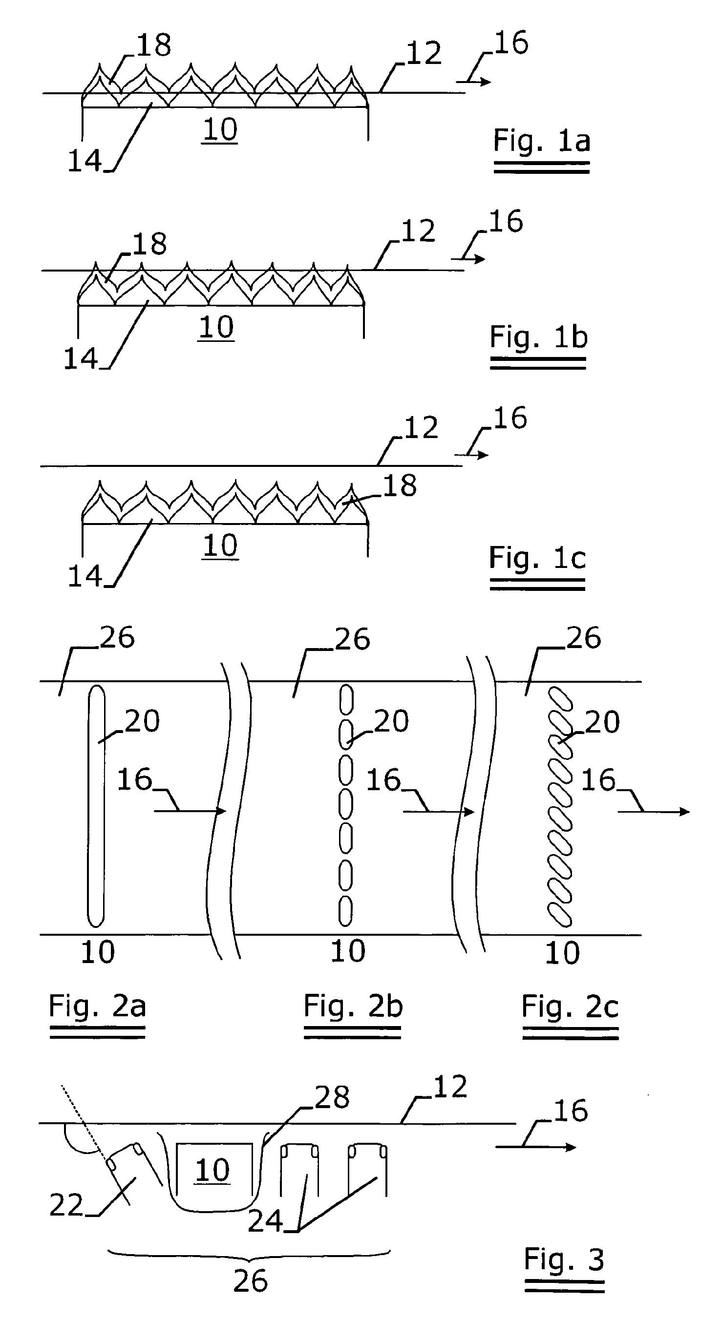
[0067]FIG. 1 represents a schematic view of the three different positions the metal fiber burner assembly can have in relation to the passing web. In FIG. 1a the web 12 passes through the flame 14 of the burner assembly 10. In FIG. 1b the web 12 passes through the tip of the flame 14. In FIG. 1c the web passes through the exhaust gases 18.

[0068]In any of the positions as depicted in FIG. 1, the web will pass a temperature zone of more than 600° C., preferably more than 700°, and higher, depending on the distance of the web to the burner assembly. Temperatures of 1500° C. and higher can thus be reached locally.

[0069]By applying such a high temperature to the web to be dried, one achieves a large temperature difference, resulting in a better heat transfer.

[0070]Considering the theoretical equation of heat transfer qx=kx. Ax.DTx, it is evident that because of the large temperature difference, the dimensions of the system can be reduced and / or the efficiency of the drying process can be...


PUM


Abstract

The object of the invention is an dryer in the dryer section (26) of a machine for treating or producing a web (12). This drying section (26) has, amongst other things, a burner assembly (10), wherein this burner assembly (10) is adapted to produce a flame (14) and exhaust gases (18). Either said flame (14) or the exhaust gases (18) or both are in direct contact with the web (12) to be dried. The flame (14) or the exhaust gases (18) or both cover the maximum width of the web (12) to be dried and this at a temperature exceeding 600° C., e.g. above 700° C., e.g. 800° C., preferably 1000° C. and more. By applying such a high temperature to the web (12) to be dried, one achieves a large temperature difference, resulting in a better heat transfer Considering the theoretical equation of heat transfer qx=kx. Ax.DTx, it is evident that because of the large temperature difference, the dimensions of the system can be reduced and/or the efficiency of the drying process can be refined. A further advantage of the higher energy transfer is that the drying process is accelerated and that the web can pass the dryer at high speeds.

Description

TECHNICAL FIELD[0001]The present invention relates to a drying section of a machine for treating or producing a material web such as paper, and more particular to airborne drying sections of such machines.BACKGROUND ART[0002]Machines for drying material web such as paper may comprise a number of mutually different sections for drying the material of the web. The technology of drying the web is usually IR-drying, contact drying using heated rotating drums, or drying by means of heated air in airborne drying sections.[0003]An airborne drying section of a machine for producing a material web such as paper, and more particular to airborne drying sections of such machines is known e.g. from U.S. Pat. No. 6,598,315 or US2001 / 0042316.[0004]The disadvantages of such presently known airborne drying sections are multiple. The heating source, providing hot gas is usually a relatively large and robust gas burning device, which provides exhaust gas to a duct system, in which the exhaust gas is d...

Claims


Application Information

Patent Timeline
Patent Type & Authority Applications(United States)
IPC IPC(8): F26B13/00
CPCD21F5/008F26B13/22F26B13/10F26B3/305
Inventor ROBIN, JEAN-PIERRELENOIR, PATRICK
Owner NV BEKAERT SA
Why Eureka
Try Eureka