Wireless Sensor Probe

a sensor and probe technology, applied in the field of wireless sensor systems, can solve the problems of ineffective means of conserving resources, over-watering and under-watering landscaping, and long installation time, and achieve the difficult methods required for a proper installation

Inactive Publication Date: 2009-01-08
HITT DALE K +1
View PDF79 Cites 89 Cited by
  • Summary
  • Abstract
  • Description
  • Claims
  • Application Information

AI Technical Summary

Problems solved by technology

In most situations this proves to be an ineffective means of conserving resources due to the inconsistent and inefficient methods followed by the operator.
In fact, quite often the operator ignores the need to suspend the watering cycle altogether, and in some cases neglects to resume the watering cycle when required, leading to both over-watered and under-watered landscaping.
It is because of this unreliable and inconvenient manual method that environmental sensors were developed that allow for an automatic interruption of the controller due to an environmental condition.
One of the major drawbacks of the conventional environmental sensors is the extensive installation time and difficult methods required for a proper installation.
If the soil is not restored properly, water and fertilizer can drain down along the hole to the sensor and corrupt the sensor readings.
Digging a hole and refilling it with slurry disrupts these strata around the sensor and decreases the accuracy of the sensor readings.
If this happens, the sensor can no longer read the soil status properly.
Sometimes, rewetting the soil is not sufficient to restore the sensor contact and the sensor must be reinstalled.
This method is burdensome in time, tools required and is prone to unsuccessful installation through poor seating of the sensor in the soil, poor representation of the target soil by the sensed soil that was disturbed by installation, and electrical noise in connecting wires.
Irrespective of a farm's size, variations in terrain, soil conditions and weather exposure produce non-uniformities of field conditions which affect the preparation and growing of crops.
However, such systems were limited in that in-ground sensors have required costly long range wireless communications systems to send data back to a central monitoring and control unit.
Therefore, it is cost prohibitive to provide a large number of sensors in order to cover a large agricultural field being processed by a large-scale irrigation device such as a center-pivot irrigation device.
Furthermore, such stationary irrigation systems are not suitable for irrigating large-scale agricultural fields due to the large number of sprinklers needed on the irrigation system.
Furthermore, an agricultural field needs to be periodically cultivated and a complex in-ground irrigation system will cause problems when the field is being turned over and prepared for its next cultivation cycle.
However, such cameras produce an array of pixels having limited resolution, and further, the cameras can only collect information periodically when weather conditions permit flight overhead.
However, the ability to collect agronomic information on a field of interest via far-distance imaging techniques often has limited capabilities.
For example, inclement weather conditions can block the ability to detect agronomic features.
For cases of satellites, the presence of cloud cover can disrupt detection of such information.
The data from these techniques is not available continuously, therefore is inappropriate for providing real-time feedback for control of irrigation systems.
In control systems, the dependence on a central controller reduces the reliability of the system because a failure in this controller brings down the system.
One problem with the use of control systems technology to distributed systems is the cost associated with developing the local communications infrastructure necessary to interconnect the various devices.
Not only is there expense associated with developing and installing appropriate sensors and actuators, but the expense of connecting functional sensors and actuators with the local controller is often prohibitive.
Another prohibitive cost is the expense associated with the expense associated with programming the local controller.

Method used


Image

  • Wireless Sensor Probe
  • Wireless Sensor Probe
  • Wireless Sensor Probe

Examples


Embodiment Construction

[0042]In accordance with the principles of the present invention, a wireless environmental monitoring and control system utilizes an array of wireless sensors for providing extended range and multiple control points within the array. The wireless environmental monitoring and control system can support sensing and irrigation control over a large area without the need for a central controller. By providing distributed monitoring and control, the control system of the present invention can be used to realize more efficient water utilization and improved crop yield.

A. Multi-hop Wireless Sensor Irrigation Control System

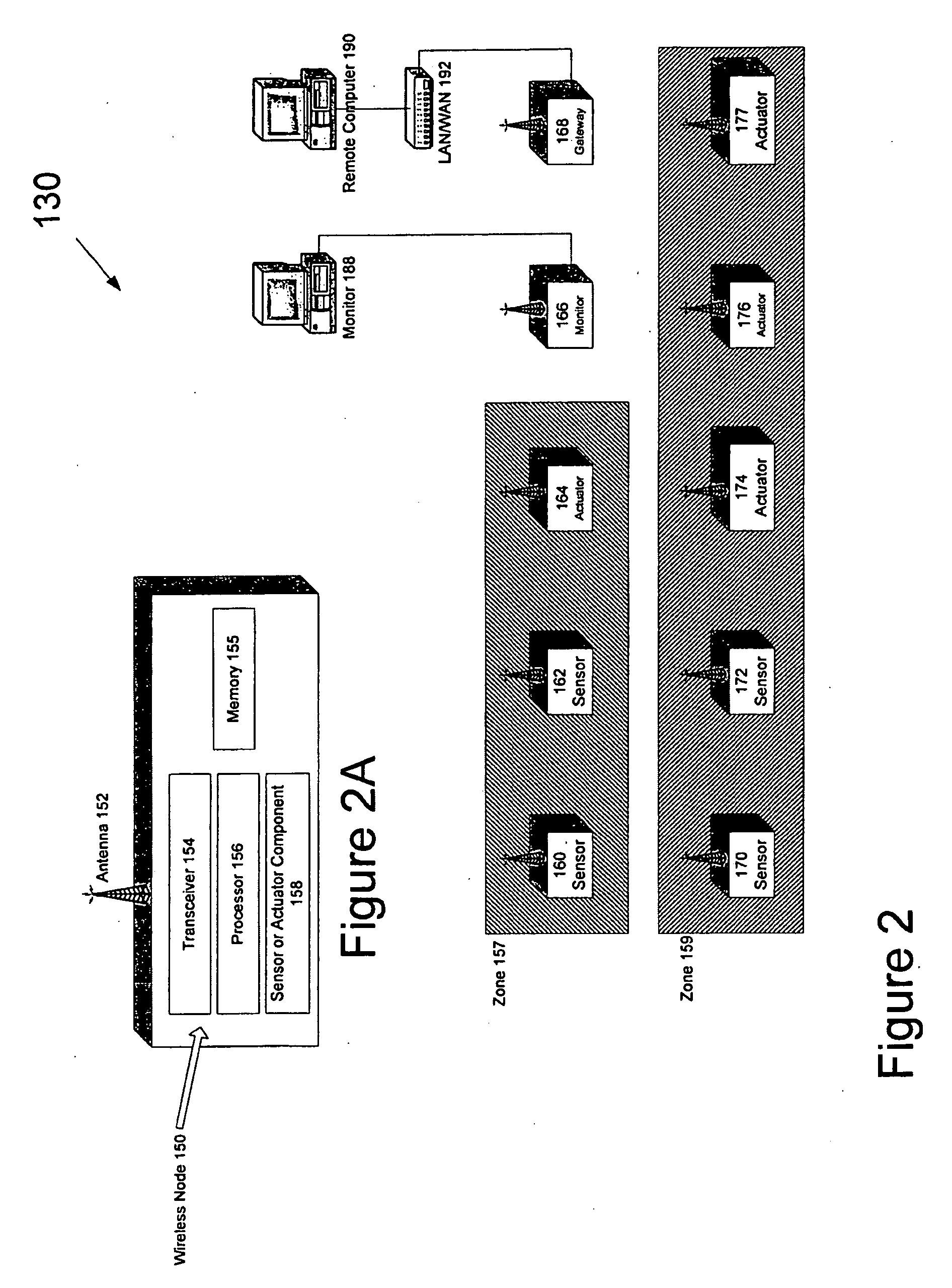
[0043]FIG. 2 is a schematic diagram of a wireless environmental monitoring and control system according to one embodiment of the present invention. In general, wireless environmental monitoring and control system 130 (system 130) is configured to include one or more irrigation zones where each irrigation zone can include one or more sensor nodes and one or more actuator no...


PUM

PropertyMeasurementUnit
areaaaaaaaaaaa
depthsaaaaaaaaaa
soil depthaaaaaaaaaa

Abstract

A wireless sensor probe for use in environmental monitoring and control includes a separable probe body and sensor mast. The probe body includes a void configured to house the sensor mast including one or more sensor devices for sensing a soil property surrounding the probe body when the probe body is inserted partially into the ground. The probe body includes a probe top part for encapsulating the probe body and the sensor mast. The sensor mast is inserted into the probe body to form the sensor probe. In another embodiment, a wireless sensor probe includes a housing containing one or more sensor devices. The probe further includes a collar situated near a top portion of the housing being used to anchor the housing to the top of the ground and a gasket formed on the outside perimeter of the housing for securing the housing in the ground.

Description

CROSS REFERENCE TO RELATED APPLICATION[0001]This application claims the benefit of U.S. Provisional Patent Application Ser. No. 60 / 421,963, filed Oct. 28, 2002, entitled “System for Environmental Monitoring and Control,” of Dale K. Hitt, which application is incorporated herein by reference in its entirety.[0002]This application is related to the following concurrently filed and commonly assigned U.S. patent applications: U.S. patent application Ser. No. ______, entitled “Wireless Sensor System For Environmental Monitoring And Control,” of Dale K. Hitt; U.S. patent application Ser. No. ______, entitled “Distributed Environmental Control In A Wireless Sensor System,” of Dale K. Hitt; U.S. patent application Ser. No. ______, entitled “Scheduled Transmission In A Wireless Sensor System,” of Dale K. Hitt; U.S. patent application Ser. No. ______, entitled “RF Based Positioning and Intrusion Detection Using A Wireless Sensor Network,” of Dale K. Hitt; and U.S. patent application Ser. No. ...

Claims


Application Information

Patent Timeline
Patent Type & Authority Applications(United States)
IPC IPC(8): G01N33/24A01G25/16
CPCG01N33/24A01G25/167
Inventor HITT, DALE K.HEATON, KURTIS G.
Owner HITT DALE K
Why Eureka
Try Eureka