Drilling System

a drilling system and drilling technology, applied in the field of drilling systems and methods, can solve the problems of process producing cuttings of a size and volume, limited horizontal reach, and large size and weight of a typical spool of coiled tubing for the hosting capacity of platforms

Inactive Publication Date: 2009-01-08
SCHLUMBERGER TECH CORP
View PDF12 Cites 30 Cited by
  • Summary
  • Abstract
  • Description
  • Claims
  • Application Information

AI Technical Summary

Problems solved by technology

However, despite significant development over the years, CTD has remained a niche application, with primary markets limited to thru-tubing re-entries wells, under balanced and slim hole drilling.
This limited expansion is due to certain inherent disadvantages of CTD:A relatively large tubing size is needed for drilling applications and only a small portion of the current global CT rig fleet is capable of handling such sizes;The size and the weight of a typical spool of coiled tubing is sometimes too great for the hosting capacity of platforms on which it is used;CTD requires surface-pumping equipment that is comparable in size to that used in conventional drilling; andCTD can only have a limited reach in horizontal wells.
These problems arise, in part, from the fact that the basic drilling process is the same as that used in a conventional, rig-based drilling system.
This means that the drilling process produces cuttings of a size and volume that still require powerful (and therefore large) surface pumping units, and large diameter coiled tubing to handle the cuttings in the borehole.
This has been required to accommodate the use of downhole electric motors for drilling and the fact that the conveyance system (wireline cable) cannot provide any weight on bit or torque reaction.

Method used


Image

  • Drilling System
  • Drilling System
  • Drilling System

Examples


Embodiment Construction

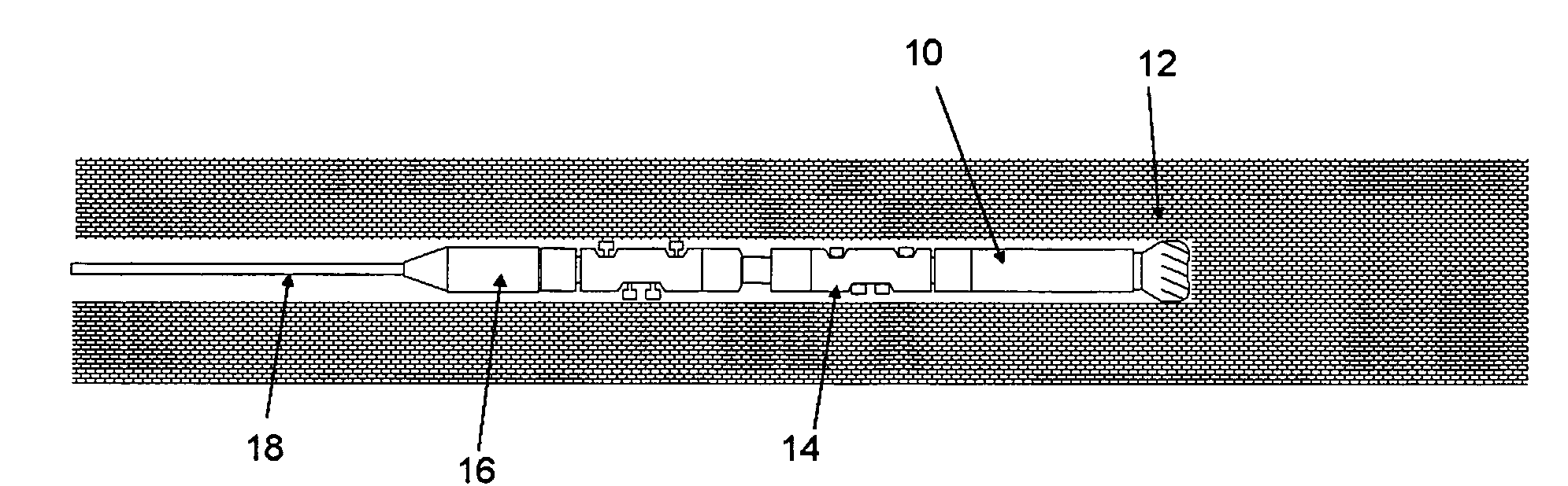
[0030]The invention is based on control of the drilling process by controlling the penetration per bit revolution (Depth of Cut control). Because the depth of cut reflects the size of the cuttings produced, such control can be used to create relatively small cuttings at all times (smaller than in conventional drilling), whose transport over a long distance requires much less power.

[0031]In conventional drilling systems (including previous CTD systems), the actual drilling operation is performed by applying controlled weight to the drill bit (WOB) that is rotated from surface or with a drilling motor to provide RPM to the bit, resulting in penetration into the formation (ROP). The torque and RPM encountered at the drill bit (TOB) is a product of the resistance of the formation and the torsional stiffness of the drill string to the rotary drilling action of the drill bit. In effect, the actively (but indirectly) controlled parameters are WOB and RPM. TOB and ROP are products of this c...


PUM


Abstract

A drilling system for drilling a borehole in an underground formation, comprises a rotary drill bit, a drilling drive mechanism that is capable of applying both rotating the drill bit and applying an axial force to the drill bit, and a control system that is capable of controlling the drive mechanism so as to control rotation of the drill bit and the axial force applied to the drill bit in order to control the depth of cut created by the drill bit when drilling through the formation. A method of drilling a borehole in an underground formation with a rotary drill bit, comprises applying rotation and an axial force to the drill bit and controlling the rotation and axial force so as to control the depth of cut created by the drill bit when drilling through the formation.

Description

TECHNICAL FIELD[0001]This invention relates to a drilling system and method that is particularly applicable to drilling with flexible conveyance systems such as wireline and coiled tubing.BACKGROUND ART[0002]Drilling using coiled tubing as a drill string was first implemented several years ago and hundreds of wells are now drilled every year with this technology. A review of the use of re-entry drilling using coiled tubing can be found in HILL, D, et al. Reentry Drilling Gives New Life to Aging Fields. Oilfield Review. Autumn 1996, p. 4-14. Coiled tubing drilling (CTO) shows many advantages compared to conventional drilling with jointed pipes, including:[0003]The ability to operate in pressurized wells;[0004]Fast tripping speeds;[0005]The ability to circulate continuously while tripping and drilling;[0006]The ability to be used in slim hole and through-tubing; and[0007]Rig-less operation.[0008]However, despite significant development over the years, CTD has remained a niche applicat...

Claims


Application Information

Patent Timeline
Patent Type & Authority Applications(United States)
IPC IPC(8): E21B7/00
CPCE21B44/02E21B4/18
Inventor LAVRUT, ERICACQUAVIVA, PIERRE-JEROMEDENOIX, HENRI
Owner SCHLUMBERGER TECH CORP
Why Eureka
Try Eureka