Particle irradiation apparatus, particle beam irradiation method and particle treatment system

Inactive Publication Date: 2009-01-08
OKAZAKI TAKASHI +5
View PDF0 Cites 30 Cited by
  • Summary
  • Abstract
  • Description
  • Claims
  • Application Information

AI Technical Summary

Benefits of technology

[0024]In accordance with the present invention, it becomes possible to form a SOBP having a steep falling edge of the dose distribution on the

Problems solved by technology

However, with the method of forming SOBPs each having a small dose distribution width and combining them to form a desired SOBP, if the Bragg peak width is spread out in order to reduce the number of layers and accordingly shorten irradiation time, the dose distribution at a boundary of a SOBP on the deep side of the irradiation region is

Method used


Image

  • Particle irradiation apparatus, particle beam irradiation method and particle treatment system
  • Particle irradiation apparatus, particle beam irradiation method and particle treatment system
  • Particle irradiation apparatus, particle beam irradiation method and particle treatment system

Examples


first embodiment

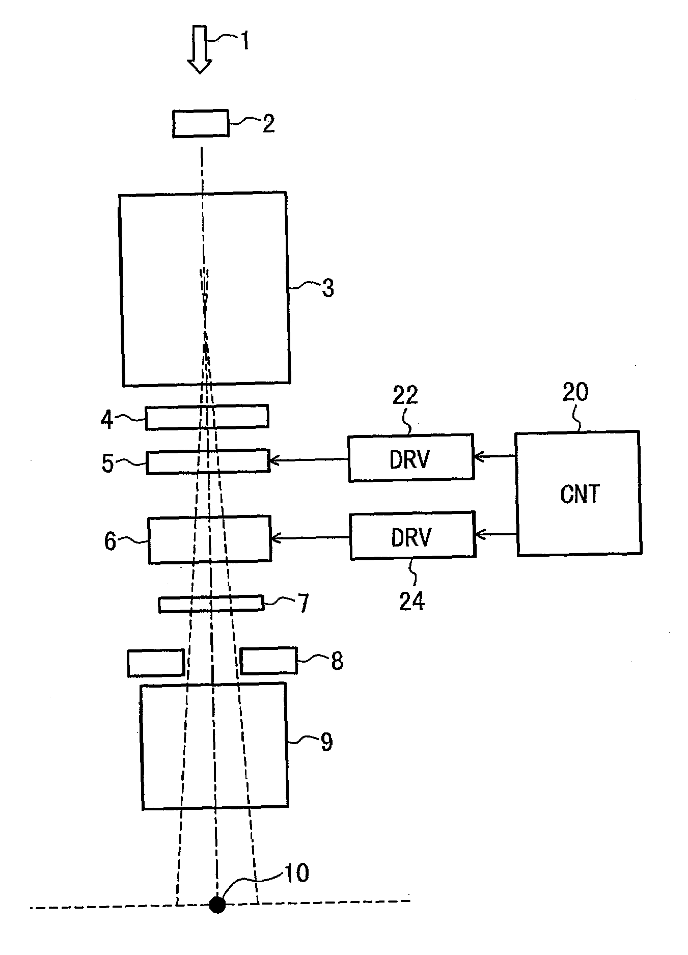
[0056]The configuration and operations of a particle irradiation apparatus according to the present invention will be explained below with reference to FIGS. 1 to 9.

[0057]First of all, the configuration of the particle irradiation apparatus according to the present embodiment will be explained below with reference to FIG. 1. Here, a particle irradiation apparatus of a proton-beam treatment system will be explained as an example. FIG. 1 shows the general configuration of an irradiation nozzle portion of the proton-beam irradiation apparatus in the proton-beam treatment system.

[0058]FIG. 1 is a block diagram showing the configuration of the particle irradiation apparatus according to the first embodiment of the present invention.

[0059]A proton beam 1 enters the proton-beam irradiation apparatus (irradiation nozzle) from the accelerator side. The proton-beam irradiation apparatus comprises: a monitors 2 such as a beam profile monitor, a scanning magnet 3 for the proton beam; a scattere...

second embodiment

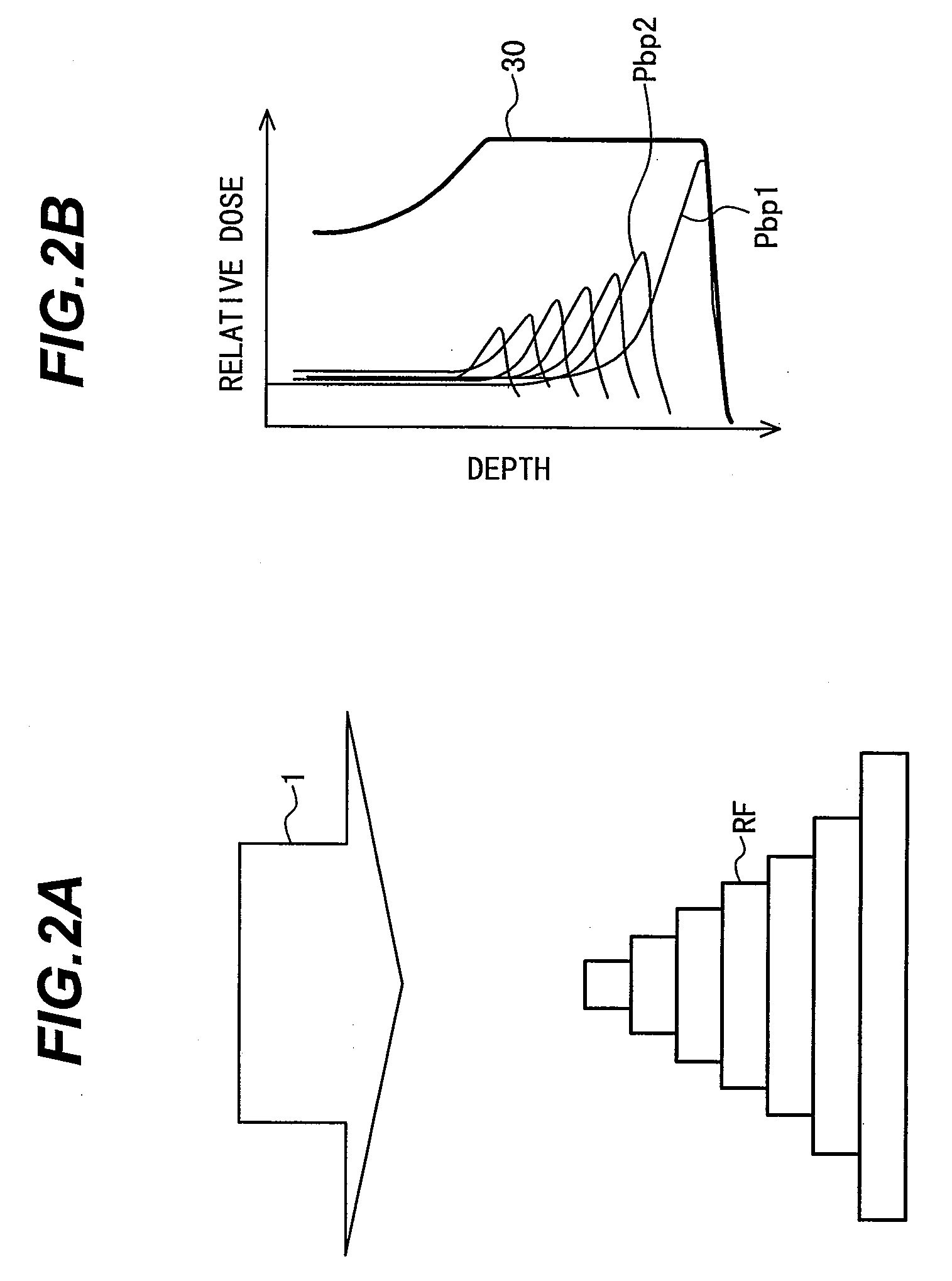
[0109]Then, the configuration and operations of a particle irradiation apparatus according to the present invention will be explained below with reference to FIGS. 10A and 10B. The configuration of the particle irradiation apparatus according to the present embodiment is the same as that of FIG. 1. The present embodiment is characterized by the configuration of the energy spread device for producing a SOBP having a small dose distribution width.

[0110]FIGS. 10A and 10B are diagrams explaining SOBPs produced by the energy spread device for producing a SOBP having a small dose distribution width used for the particle irradiation apparatus according to the second embodiment of the present invention.

[0111]The spread width of a SOBP having a small dose distribution width to be produced can be changed by controlling the number, width, and height of layers of energy spread devices for producing a SOBP having a small dose distribution width. For example, the number and width of layers are in...

third embodiment

[0117]Then, the configuration and operations of a particle irradiation apparatus according to the present invention will be explained below with reference to FIGS. 11A and 11B. The configuration of the particle irradiation apparatus according to the present embodiment is the same as that of FIG. 1. The present embodiment is characterized by the configuration of the energy spread device for producing a SOBP having a small dose distribution width.

[0118]FIGS. 11A and 11B are diagrams explaining SOBPs produced by the energy spread device for producing a SOBP having a small dose distribution width used for the particle irradiation apparatus according to the third embodiment of the present invention.

[0119]In a first example of the present embodiment, the shape of the dose distribution is changed. Here, the energy spread device for producing a SOBP having a small dose distribution width shown in FIG. 4 is employed; however, the proton beam intensity is increased, or the irradiation dose is...


PUM


Abstract

A particle irradiation apparatus and a particle beam irradiation method that controls the energy and irradiation dose of a particle beam to form a high dose region having a high uniformity of depth-directional spread (Spread Out Bracici Peak, referred to as SOBP). A SOBP having a steep falling edge of the dose distribution on the deep side from the body surface is formed based on a method of superimposing SOBPs each having a small dose distribution width to form a desired SOBP. An energy-spread-device forms a first SOBP having a small dose distribution width; and an energy spread device 2 forms a second SOBP having a small dose distribution width and a steep falling edge of the dose distribution at the deepest portion from the body surface. The thus formed SOBPs are superimposed to form a SOBP having a length suitable for the target region.

Description

BACKGROUND OF THE INVENTION[0001]1. Field of the Invention[0002]The present invention relates to a particle irradiation apparatus, a particle beam irradiation method and a particle treatment system. More particularly, the present invention is concerned with a particle irradiation apparatus, a particle beam irradiation method and a particle treatment system which are suitable for forming a high dose region in a dose distribution by use of a ridge filter.[0003]2. Description of the Related Art[0004]A particle treatment system, for example, a proton-beam treatment system, is one of the effective means for cancer treatment and is expected to be more increasingly used in the future. With the proton-beam treatment, it is demanded that the dose distribution in an affected part of patient's body (target region) be controlled to a uniform or predetermined state.[0005]Methods of controlling the dose distribution to a uniform state, etc., include using a scatterer to spread out a proton beam o...

Claims


Application Information

Patent Timeline
IPC IPC(8): A61N5/00
CPCA61N5/10A61N2005/1095A61N2005/1087
Inventor OKAZAKI, TAKASHIFUJIMAKI, HISATAKAFUJITAKA, SHINICHIROFUJIMOTO, RINTAROFUJII, YUSUKEHIRAMOTO, KAZUO
Owner OKAZAKI TAKASHI
Why Eureka
Try Eureka