Roller chain and sprocket system

Inactive Publication Date: 2009-01-08
HIGH ARCTIC ENERGY SERVICES
View PDF36 Cites 47 Cited by
  • Summary
  • Abstract
  • Description
  • Claims
  • Application Information

AI Technical Summary

Benefits of technology

[0012]Embodiments of the invention utilize interconnectable roller chain links for forming an articulated roller chain. Each of the links bears upon an adjacent link, when aligned linearly, for forming a substantially rigid pushing column. The column is engaged at a linear portion thereof by one or more co-operating sprockets having teeth with an involute profile suitable for driving the

Problems solved by technology

Applicant believes Novick's device has a low teeth to pinion diameter ratio and is similarly subject to side loading which diminishes the efficiency of the vertical translation.
Applicant believes that the EDM arrangement is prone to high sliding contact stresses between the gear teeth and the rack teeth.
Typically pairs of opposing pinions are

Method used


Image

  • Roller chain and sprocket system
  • Roller chain and sprocket system
  • Roller chain and sprocket system

Examples


examples

Roller Chain Links

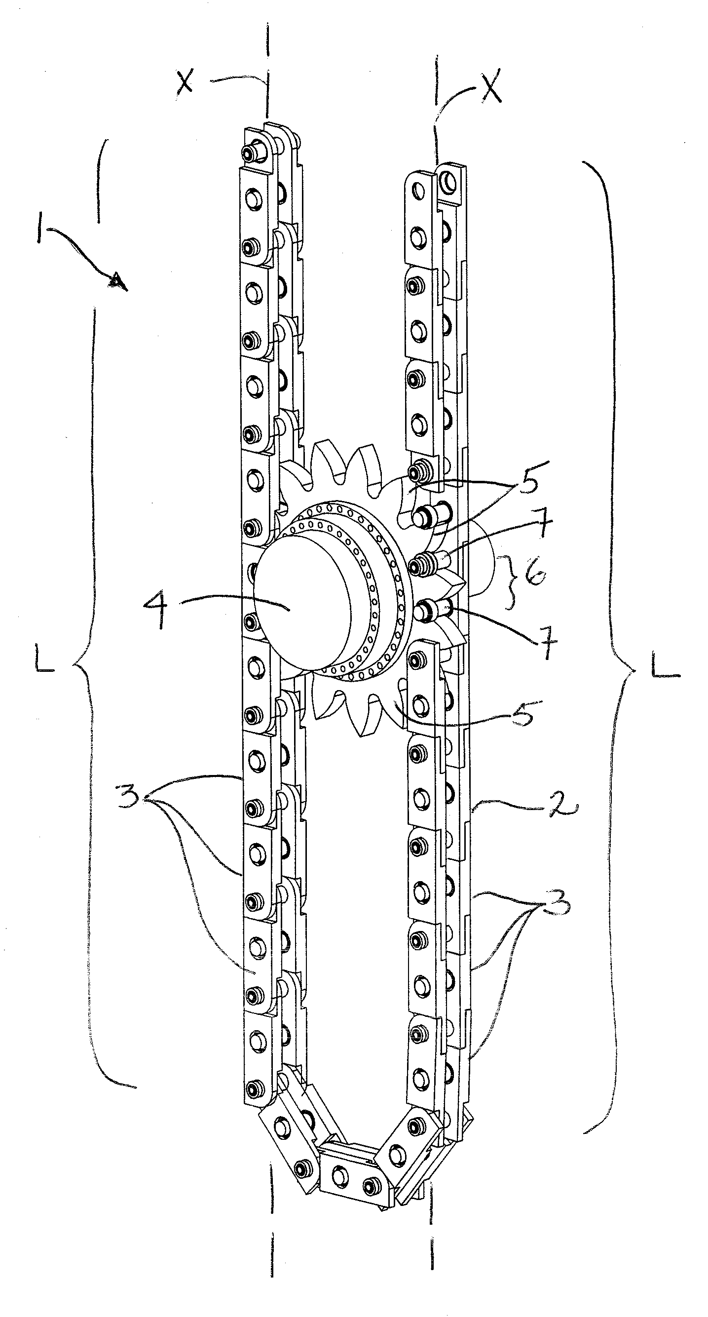
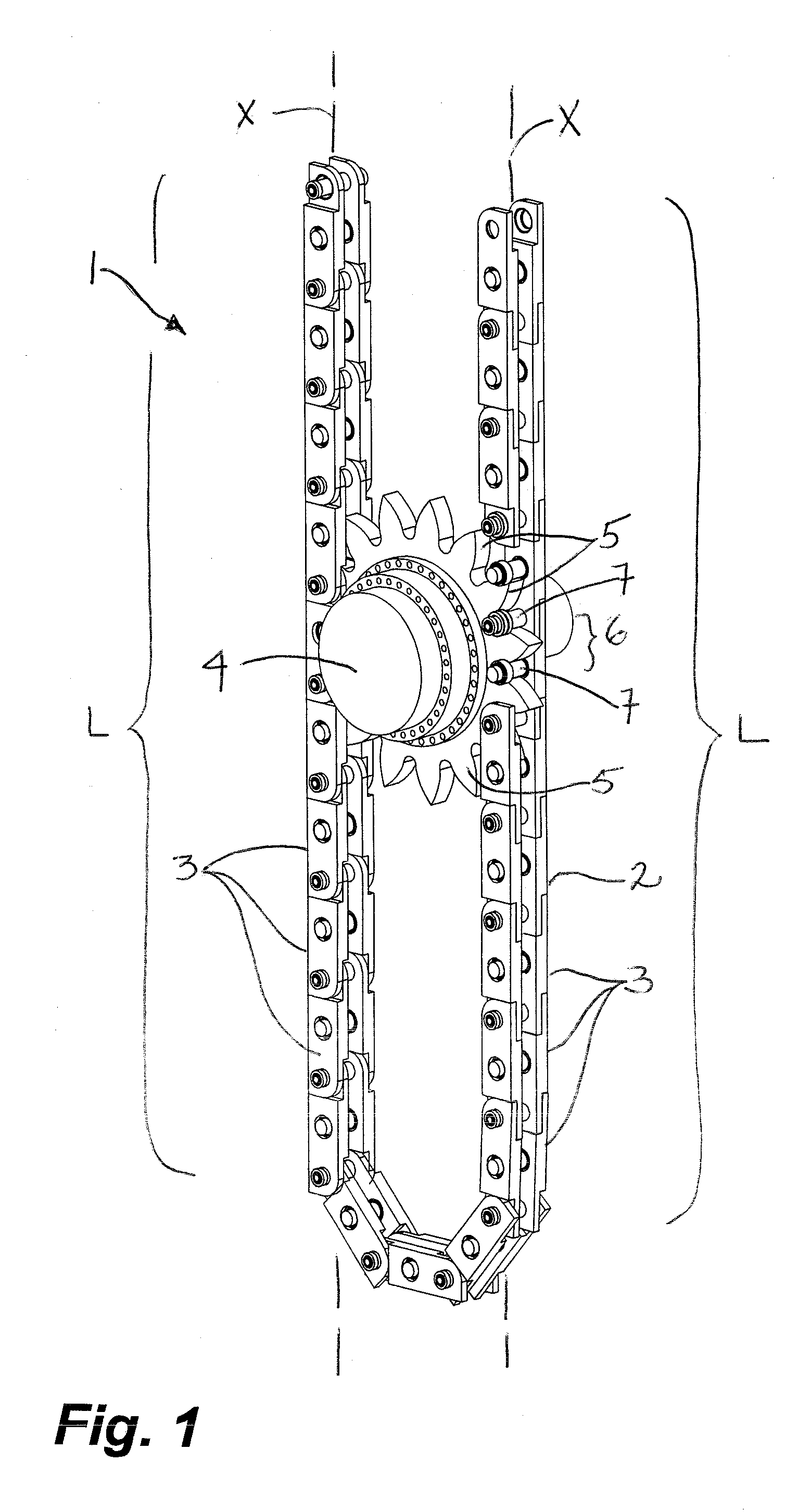
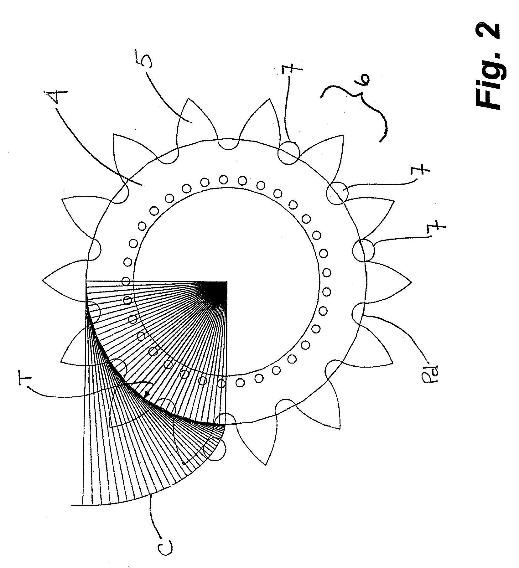
[0055]As shown in FIGS. 5, 6A-6C and 10, the plurality of rollers 7 and the one or more frame members 10 may be arranged to engage the teeth 5 on one sprocket 4 or on more than one sprocket 4.

[0056]As shown in FIG. 5, the links 3 comprise two, spaced-apart frame members 10,10 and a plurality of transversely extending rollers 7 connecting therebetween. The rollers 7 in each link 3 are spaced along the frame members 10,10 to form a linear series of voids 6 for receiving teeth 5 of a single driven sprocket 4. Each of the frame members 10,10 has a groove member 15 and a tongue member 13 which extending linearly outwardly at opposing ends 14,16 of the frame members 10,10.

[0057]In the embodiment shown, three pins or rollers 7 are used to create two voids 6 into which the sprocket teeth 5 are received for engagement with the rollers 7.

[0058]Further, in embodiments of the invention, the rollers 7 are supported on bearings 20 fit to the frame member 10 in such a manner that...


PUM


Abstract

A roller chain and sprocket system utilizes an involute profile on the sprocket teeth to engage rollers in the links of a roller chain. The links, when aligned linearly, bear upon one another when pushed to form a substantially rigid column which has an axis. The system results in substantially 100% of the rotational energy imparted to the sprocket being translated into linear motion of the chain along the column axis.

Description

CROSS REFERENCE TO RELATED APPLICATION[0001]This application is a regular application claiming priority of U.S. Provisional Patent application Ser. No. 60 / 942,618, filed on Jun. 7, 2007, the entirety of which is incorporated herein by reference.FIELD OF THE INVENTION[0002]Embodiments of the invention relate to chains and sprockets used for translating a load and, more particularly, to a chain and sprocket for lifting and lowering a load vertically in a mast of a drilling rig.BACKGROUND OF THE INVENTION[0003]A multitude of different chain and sprocket drives are known in many industries for pushing and pulling a load. Many design considerations must be taken into account depending upon the size of the load to be moved and the direction in which it is to be moved.[0004]Typically, the links of a flexible chain must interlock to achieve vertical translation. One such interlocking hoisting chain design is taught in U.S. Pat. No. 1,427,642 to Rickard. In use, the chain length unravels fro...

Claims


Application Information

Patent Timeline
IPC IPC(8): B66F3/00
CPCB66F3/06E21B3/02F16H55/30F16H7/06F16G13/20F16H19/0636E21B3/022
Inventor YOUNG, DARRENWOOD, JED
Owner HIGH ARCTIC ENERGY SERVICES
Why Eureka
Try Eureka