Piezoelectric vibrating pieces and piezoelectric devices

a piezoelectric and vibrating piece technology, applied in piezoelectric/electrostrictive/magnetostrictive devices, piezoelectric/electrostriction/magnetostriction machines, electrical apparatus, etc., can solve the problem of not improving the variability of ci value, and achieve the effect of small area to be conducted with electrically conductive adhesives

Inactive Publication Date: 2009-01-08
NIHON DEMPA KOGYO CO LTD
View PDF7 Cites 14 Cited by
  • Summary
  • Abstract
  • Description
  • Claims
  • Application Information

AI Technical Summary

Benefits of technology

[0010]According to the configuration of the second aspect, by making the width of the base electrode than of exciting electrode narrow, the area to be conducted with the electrically conductive adhesive can be small.
[0011]The base electrode of piezoelectric vibrating piece of third aspect is extended to only the middle of another end from the one end of the base portion. According to the configuration of the third aspect, by making the width of base electrode extended from the exciting electrode shorter than the exciting electrode, the area to be conducted with the electrically conductive adhesive can be small.

Problems solved by technology

However, as disclosed in Japan Unexamined Patent Application No. 2004-266871, even the tuning-fork type piezoelectric vibrating piece having a notch on the base portion has large variability of CI value, and even compared to a tuning-fork type piezoelectric vibrating piece without having a notch, the variability of CI value is not improved.
However, in some examples, other featured and advantages are realized, and other problems may be solved.

Method used


Image

  • Piezoelectric vibrating pieces and piezoelectric devices
  • Piezoelectric vibrating pieces and piezoelectric devices
  • Piezoelectric vibrating pieces and piezoelectric devices

Examples


fourth embodiment

[0049]A first base electrode 23a4 and second base electrode 25a4 formed on the second base portion 29-2 of a fourth embodiment is a L-shape and the width of electrode is 0.01 mm to 0.10 mm. In FIG. 5B, the area where the electrically conductive adhesive 31 conducts to the first base electrode 23a4 and the second base electrode 25a4 is about 10%. Such first base electrode 23a4 and second base electrode 25a4 have low CI value variability and the ZCT variability becomes low.

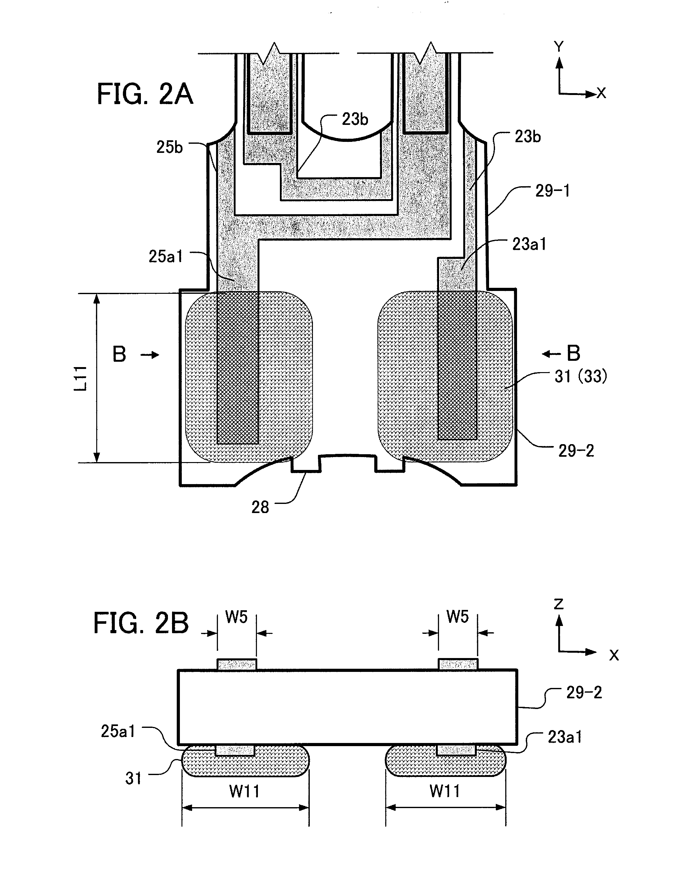
[0050]FIGS. 6A-6B are enlarged views of the second base portion 29-2 of a fifth embodiment. FIG. 6A shows a back surface (the surface to be adhered) of the second base portion 29-2, FIG. 6B is a front surface, and FIG. 6C is a cross-sectional view taken from C-C line of FIG. 6B. On the second base portion 29-2 of a sixth embodiment, the shapes of base electrodes on the front and back surface are different. As FIG. 6A shows, the first base electrode 23a1 and the second base electrode 25a1 are as same shapes as of the...

first embodiment

[0051]As shown in FIG. 6C, the conduct of the electrically conductive adhesive 31 and the first base electrode 23a1 and the second base electrode 25a1 is the same as the first embodiment, so the CI value variability and ZCT variability become lower.

[0052]FIGS. 7A-7B are enlarged views of the second base portion 29-2 of a sixth embodiment. FIG. 7A is a back surface of the second base portion 29-2 and FIG. 7B is a cross sectional view taken from B-B line of FIG. 7A. The first base electrode 23a5 and the second base electrode 25a5 are base electrodes having large dimension as previous electrode have. If the electrically conductive adhesive 31 is applied to the electrodes with this condition, the variability of CI value and ZTC become wide. Therefore, an insulating layer 37 is coated at least on the back surface of the first base electrode 23a5 and the second base electrode 25a5 where the electrically conductive adhesive 31 is applied. The insulating layer 37 is preferably made of oxide...

third embodiment

[0058]If the conducting area is more than 1%, the tuning-fork type crystal vibration piece 20 can be actually excited, so the minimum limit of dimension ratio of the base electrode corresponding the electrically conductive adhesive 31 is 1%. On the contrary, if the dimension ratio of the base electrode corresponding the electrically conductive adhesive 31 is more than 80%, especially the variability of ZCT of the third embodiment becomes 1.0 and the difference becomes smaller compared to the previous base electrode. So, the maximum limit of dimension ratio of the base electrode corresponding the electrically conductive adhesive 31 is 80%. As is shown by FIGS. 8B and 8C, 5% to 50% of the dimension ratio of the base electrode corresponding the electrically conductive adhesive 31 is preferable.

[0059]FIG. 9 is a plan view showing an embodiment of the second tuning-fork type crystal vibrating piece 120. The same components of configuration use the same numbers used in FIG. 1A and others....


PUM


Abstract

The piezoelectric vibrating piece (20) comprises a base portion (29) having an adhesive area on a first surface of electrically conductive adhesive 31 for mounting, a pair of vibrating arms (21) extending in a first direction from one edge of the base portion, base electrodes (23a, 25a) arranged in the base portion, an exciting electrode (23c, 25c) extending in a first direction and connecting the base electrode to excite a pair of vibrating arms. The area where the base electrodes (23a, 25a) conduct the electrically conductive adhesive (31) is smaller than the adhesive area (33).

Description

CROSS-REFERENCE TO RELATED APPLICATION[0001]This application claims the benefit of Japanese Patent Application No. 2007-173863 filed on Jul. 2, 2007 in the Japan Patent Office, the disclosure of which is incorporated herein in its entirety by reference.FIELD OF THE INVENTION[0002]The present invention relates to improvement of a piezoelectric vibrating piece and a piezoelectric device accommodating the piezoelectric vibrating piece inside of the package.DESCRIPTION OF THE RELATED ART[0003]For small information device, such as HDD (Hard Disc Drive), mobile computers, or IC cards, or clock sources of mobile phones, piezoelectric devices such as a piezoelectric vibrating piece or a piezoelectric oscillator is being used.[0004]A tuning-fork type piezoelectric vibrating piece disclosed in Japan Unexamined Patent Application No. 2001-203560 is formed the tuning-fork type outer shape by wet etching a piezoelectric material such as a crystal wafer. In order to lower crystal impedance (CI) v...

Claims


Application Information

Patent Timeline
Patent Type & Authority Applications(United States)
IPC IPC(8): H01L41/053
CPCH03H9/21
Inventor KAWANISHI, SHINGOIWAI, YUICHIKAWA, RYOICHI
Owner NIHON DEMPA KOGYO CO LTD
Why Eureka
Try Eureka