Radar System

a radar system and unnecessary signal technology, applied in the field of radar systems, can solve the problems of difficult to stably suppress clutter spectrum, difficult to circumvent problems, difficult to separate true objects from clutter, etc., and achieve the effect of sufficient resolution of continuous wave radar systems, suppression of unnecessary waves, and high resolution

Inactive Publication Date: 2009-01-08
MITSUBISHI ELECTRIC CORP
View PDF2 Cites 21 Cited by
  • Summary
  • Abstract
  • Description
  • Claims
  • Application Information

AI Technical Summary

Benefits of technology

[0013]Here, the continuous waves in this description may be one of the FMCW, the 2-frequency CW and the stepped chirp continuous waves. Radar systems, whichever continuous waves are used, can achieve at the same time high resolution and suppression of unnecessary waves by adopting features of the present invention.
[0014]Because a radar system according to the present invention classifies on the basis of the spectral spread correspondin

Problems solved by technology

In the system according to Patent Document 1, when multiple objects exists in a specified detection zone, observed frequencies from moving objects become identical to a clutter spectrum, depending on combinations of distance to and velocity of the objects, which causes a problem in that it is difficult to stably suppress the clutter spectrum.
Therefore, as long as continuous waves are assumed, it is difficult to circumvent the problem in that separation of true objects from the clutter is difficult.
The system according to Patent Document 2 has a feature in that a slope period, during whic

Method used


Image

  • Radar System
  • Radar System
  • Radar System

Examples


embodiment 1

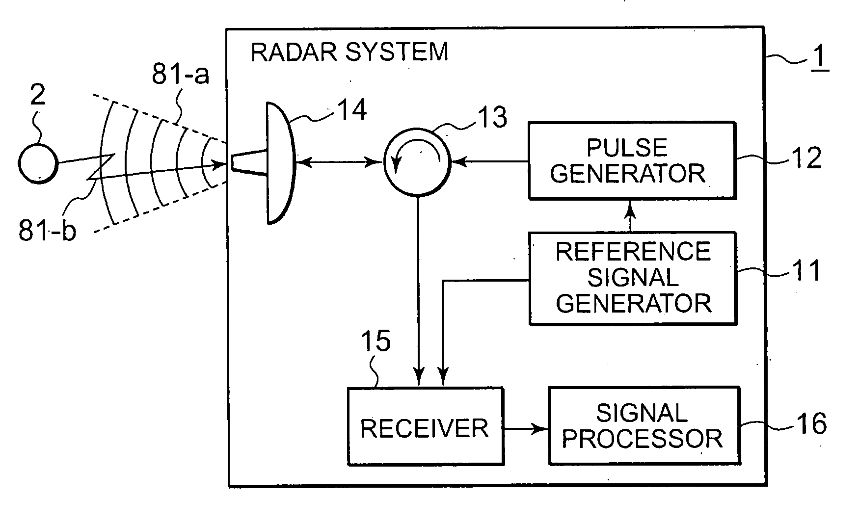
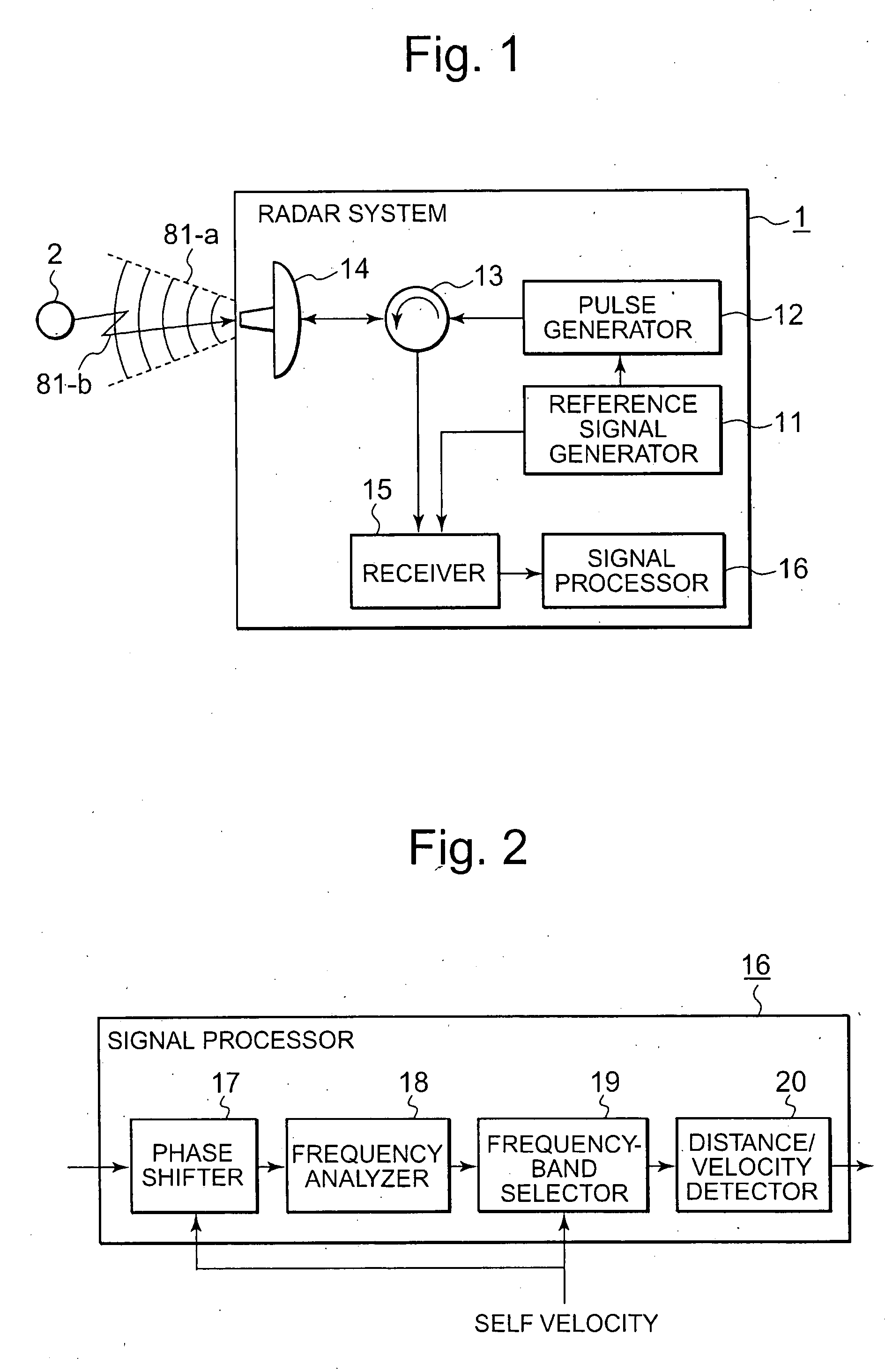
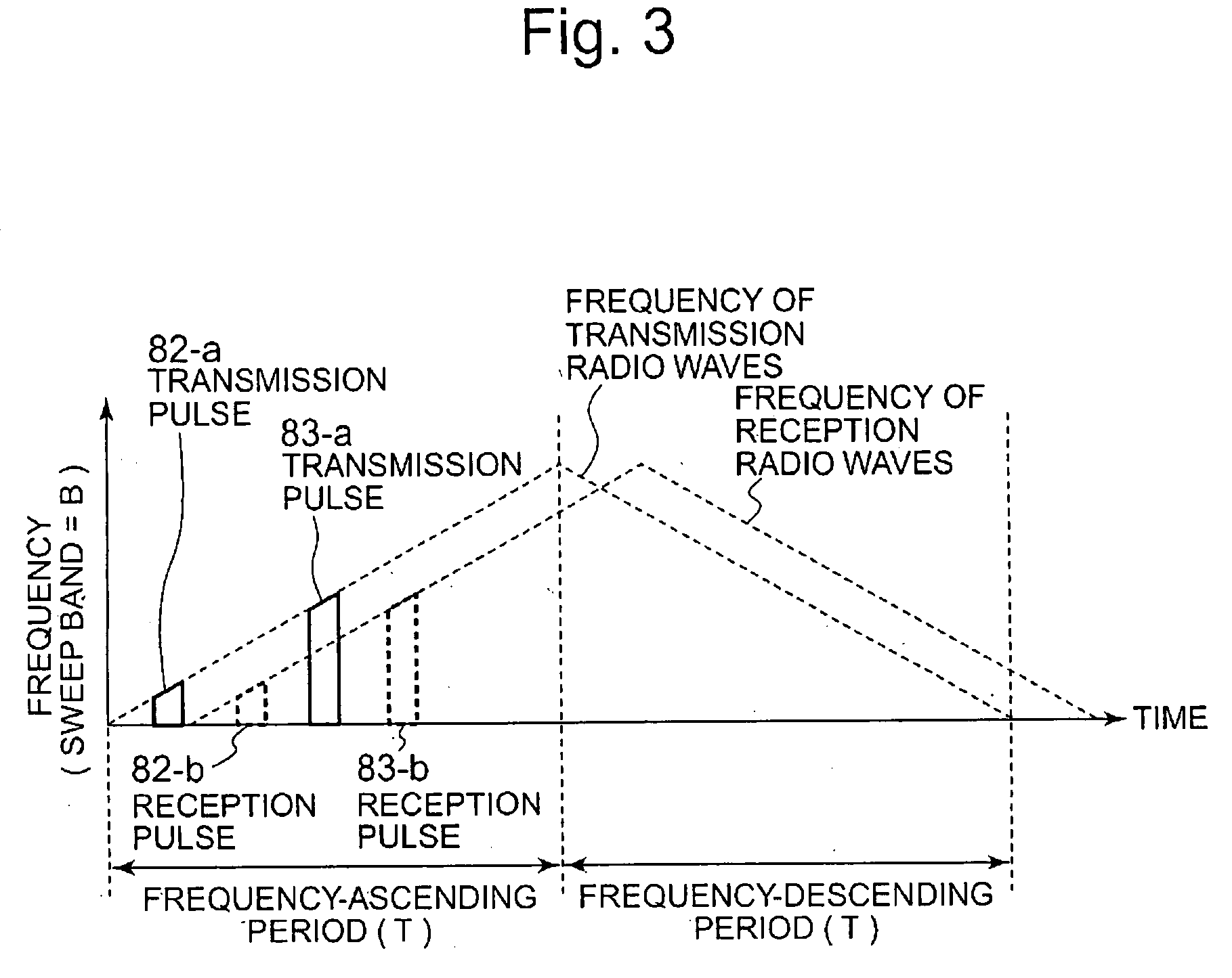
[0025]FIG. 1 is a configurational block diagram illustrating a radar system according to Embodiment 1 of the present invention. A radar system 1 in the diagram is a radar system mounted on a moving object (also referred as a moving platform) that moves at a velocity of ν0; and includes a reference signal generator 11, a pulsing device 12, a circulator 13, an antenna 14, a receiver 15, and a signal processor 16. The reference signal generator 11 is a circuit or an elemental device that generates a reference signal having a predetermined continuous waveform. The frequency of the reference signal generated by the reference signal generator 11 repeats in a certain cycle to continuously ascend and descend. A radar system, using such frequency-modulated waves, that measures relative distance to and relative velocity of an external object has been known as a FMCW radar system.

[0026]The pulse generator 12 is a circuit or an elemental device that transforms into a pulsed signal having predet...

embodiment 2

[0080]In Embodiment 2 according to the present invention, it will be explained that 2-frequency CW radar systems can also suppress unnecessary radio waves by dividing into bands output channels from FFT operations of beat frequencies.

[0081]The configuration of a radar system according to Embodiment 2 of the present invention is also illustrated by the block diagram of FIG. 1, in the same way as Embodiment 1. However, Embodiment 2 according to the invention differs from Embodiment 1 in the configuration of the signal processor 16. FIG. 5 is a configurational block diagram illustrating such a signal processor 16 according to Embodiment 2 of the present invention. As is apparent from its comparison with the configuration, illustrated in FIG. 2, of the signal processor in Embodiment 1, the signal processor 16 according to Embodiment 2 of the present invention has a feature in that the phase shifter 17 has been eliminated.

[0082]Next, the operation of the radar system 1 according to Embod...

embodiment 3

[0092]Next, as another aspect of the present invention, a radar system in which an HPF (high pass filter) is used will be explained in Embodiment 3.

[0093]A configuration of the radar system according to Embodiment 3 of the present invention is also illustrated by the block diagram of FIG. 1, in the same way as Embodiment 1. However, Embodiment 3 according to the prevent invention differs from Embodiment 1 in the configuration of the signal processor 16. FIG. 7 is a configurational block diagram illustrating a detailed configuration of the signal processor 16 in the radar system according to Embodiment 3 of the present invention. In the figure, comparing to that of Embodiment 1, its new aspect is that an HPF (high pass filter) 21 is newly provided. Also in the radar system according to Embodiment 3, information on velocity from a self-velocity sensor, not illustrated in the figure, is inputted into the HPF 21. Since the other configurational components are the same as those in Embodi...


PUM


Abstract

By pulsing transmission radio waves of continuous wave radar, clutter components included in a reception signal are suppressed.
In a radar system that emits into space pulsed transmission radio waves being generated based on a frequency-modulated reference continuous waveform, acquires a reception signal by receiving the pulsed transmission radio waves reflected from an external object, and computes distance thereto and velocity thereof from the frequency of a beat signal obtained by mixing the acquired reception signal with the reference continuous waveform, the radar system includes a frequency-band selector 19 for classifying, on the basis of a spectral spread corresponding to the pulse width of the pulsed transmission radio waves, frequency components of the beat signal, and a distance/velocity calculator 20 for computing, on the basis of the classified results from the frequency-band selector 19, relative distance to and velocity of a moving object, or relative distance to a stationary object.

Description

TECHNICAL FIELD[0001]The present invention relates to technologies for suppressing unnecessary signals in radar system, especially to a radar technology that achieves at the same time, by combining the characteristics of pulse radars with those of continuous wave radars, resolution characterized by continuous wave radars and unnecessary-signal suppression characterized by pulse radars.BACKGROUND ART[0002]To avoid collision while driving, a vehicle cruise control system or a driver assistant system has been studied to put into commercial use. In such systems to avoid collision, automotive radar technologies play an important role that detects relative velocity of and distance to obstacles. In automotive radars, it is demanded that they can easily be mounted at low cost, and is also demanded that they apply systems capable of detecting, with sufficient resolution, distance to and velocity of obstacles.[0003]As for automotive radar systems, such as pulse radar, pulse-compression radar ...

Claims


Application Information

Patent Timeline
IPC IPC(8): G01S13/58
CPCG01S13/34G01S13/584G01S13/536
Inventor INABA, TAKAYUKI
Owner MITSUBISHI ELECTRIC CORP
Why Eureka
Try Eureka