Zero-voltage-switching electric converter
- Summary
- Abstract
- Description
- Claims
- Application Information
AI Technical Summary
Benefits of technology
Problems solved by technology
Method used
Image
Examples
first embodiment
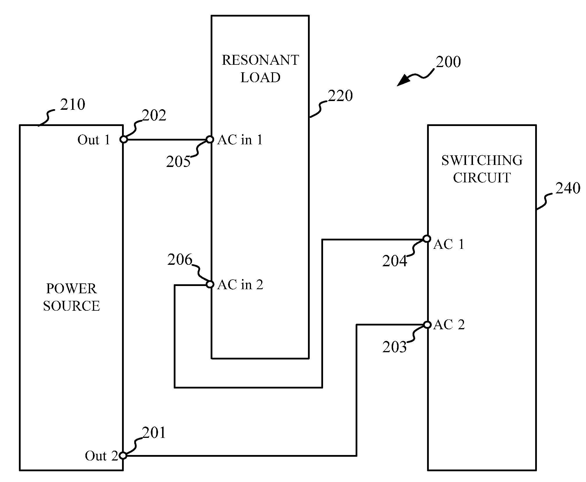
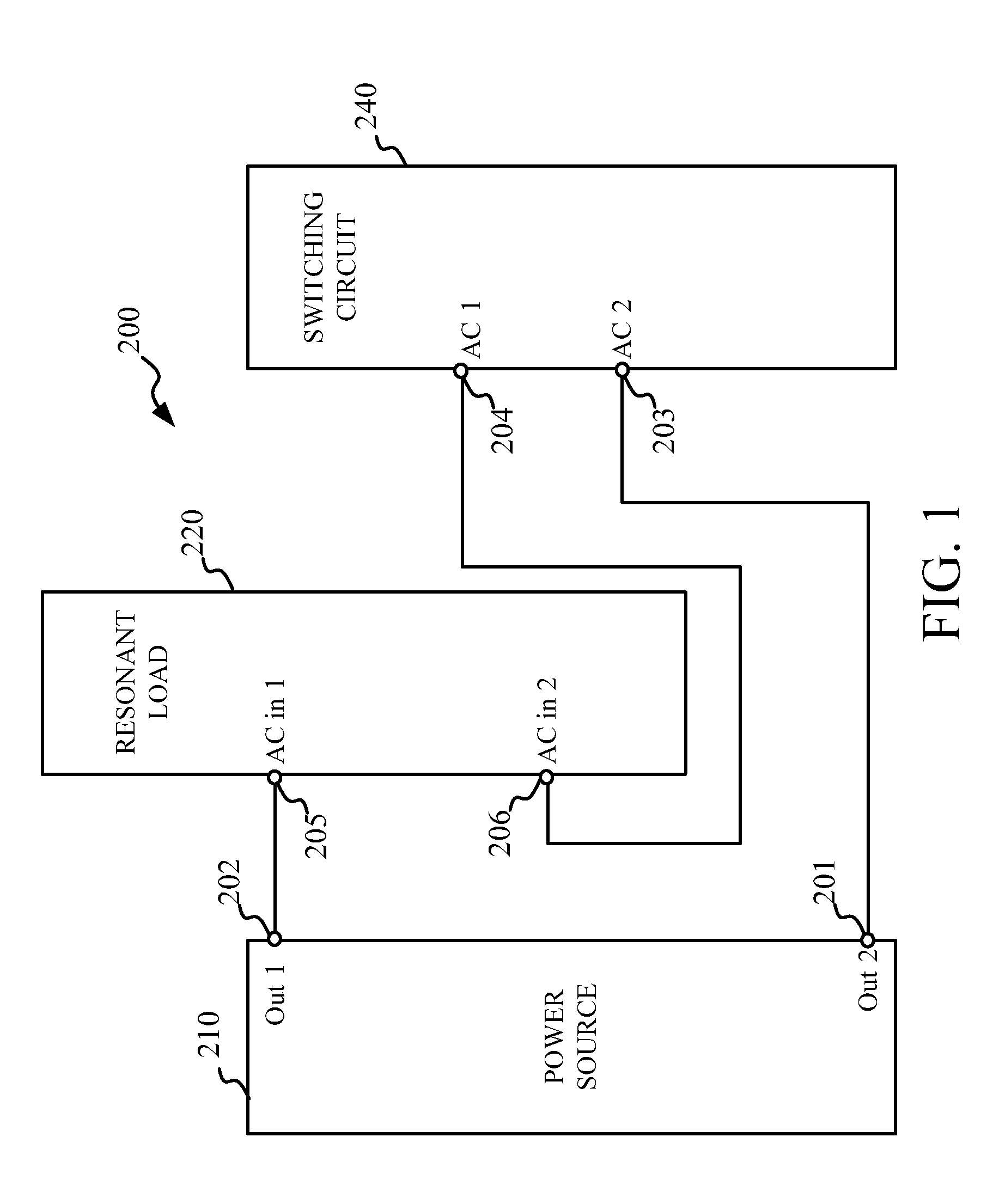
[0031]FIG. 3 is a circuit diagram showing the circuit configuration of a zero-voltage-switching electrical converter 10 according to the present invention. The zero-voltage-switching electric converter 10 comprises a DC power source 12, a switching circuit 40 electrically connected to the DC power source 12, and a resonant load 20 electrically connected to the power source 12 and the switching circuit 40. The resonant load 20 includes a first capacitor 22, a first inductor 24 connected in series to the first capacitor 22, a load 26 such as a backlight CCFL (cold cathode fluorescent lamp) coupled to the first capacitor 22 via a transformer 30. The transformer 30 includes a primary winding 32 connected in parallel to the first capacitor 22 and a secondary winding 34 connected in parallel to the load 26.
[0032]In one embodiment of the present disclosure, the switching circuit 40 comprises a switch-pair 42 including an upper switch 44 and a lower switch 46 connected in series to the uppe...
second embodiment
[0035]FIG. 5 is a circuit diagram showing the circuit configuration of a zero-voltage-switching electrical converter 50 according to the present invention. In comparison with the zero-voltage-switching electrical converter 10 shown in FIG. 3, the zero-voltage-switching electrical converter 50 shown in FIG. 5 has a different resonant load 60. The resonant load 60 comprises a second inductor 62 connected in parallel to the first capacitor 22 and a third inductor 64 connected in series to the load 26. Particularly, the load 26 is coupled to the first capacitor 22 via the second inductor 62 together with the third inductor 64, rather than via the transformer 30.
third embodiment
[0036]FIG. 6 is a circuit diagram showing the circuit configuration of a zero-voltage-switching electrical converter 70 according to the present invention. The zero-voltage-switching electrical converter 70 comprises an AC power source 72 and a third capacitor 76 connected in parallel to the AC power source via a filter 78. In addition, the zero-voltage-switching electrical converter 70 uses a switching circuit 80 having a half bridge boost topology rather than the switching circuit 40 in comparison with the zero-voltage-switching electrical converter 10 shown in FIG. 3. The half bridge boost inverter 80 comprises a capacitor-pair 83 connected in parallel to the switch-pair 42 The capacitor-pair 83 includes an upper capacitor 82 and a lower capacitor 84 connected in series to the upper capacitor 82, the resonant load 20 is connected to a junction 86 between the upper switch 44 and the lower switch 46, and the AC power source 72 is connected to a junction 88 between the upper capacit...
PUM
 Abstract
Description
Claims
Application Information
 - R&D Engineer
- R&D Manager
- IP Professional
- Industry Leading Data Capabilities
- Powerful AI technology
- Patent DNA Extraction
Browse by: Latest US Patents, China's latest patents, Technical Efficacy Thesaurus, Application Domain, Technology Topic, Popular Technical Reports.
© 2024 PatSnap. All rights reserved.Legal|Privacy policy|Modern Slavery Act Transparency Statement|Sitemap|About US| Contact US: help@patsnap.com


