
MR-compatible video system

a video system and compatible technology, applied in the field of mr-compatible video systems, can solve the problems of increasing the noise level of patients, increasing the burden on patients, and affecting the patient's comfort, and achieve the effect of simple realization

Inactive Publication Date: 2009-01-08
SIEMENS AG
View PDF10 Cites 4 Cited by
  • Summary
  • Abstract
  • Description
  • Claims
  • Application Information

AI Technical Summary

Benefits of technology

[0011]A little closer to reality is a further embodiment in which the image signals depict an examination room, a magnetic resonance device located in the examination room being depicted semi-transparently. The patient thus obtains a feeling of the magnetic resonance device surrounding him without significantly hindering the view in the examination room.
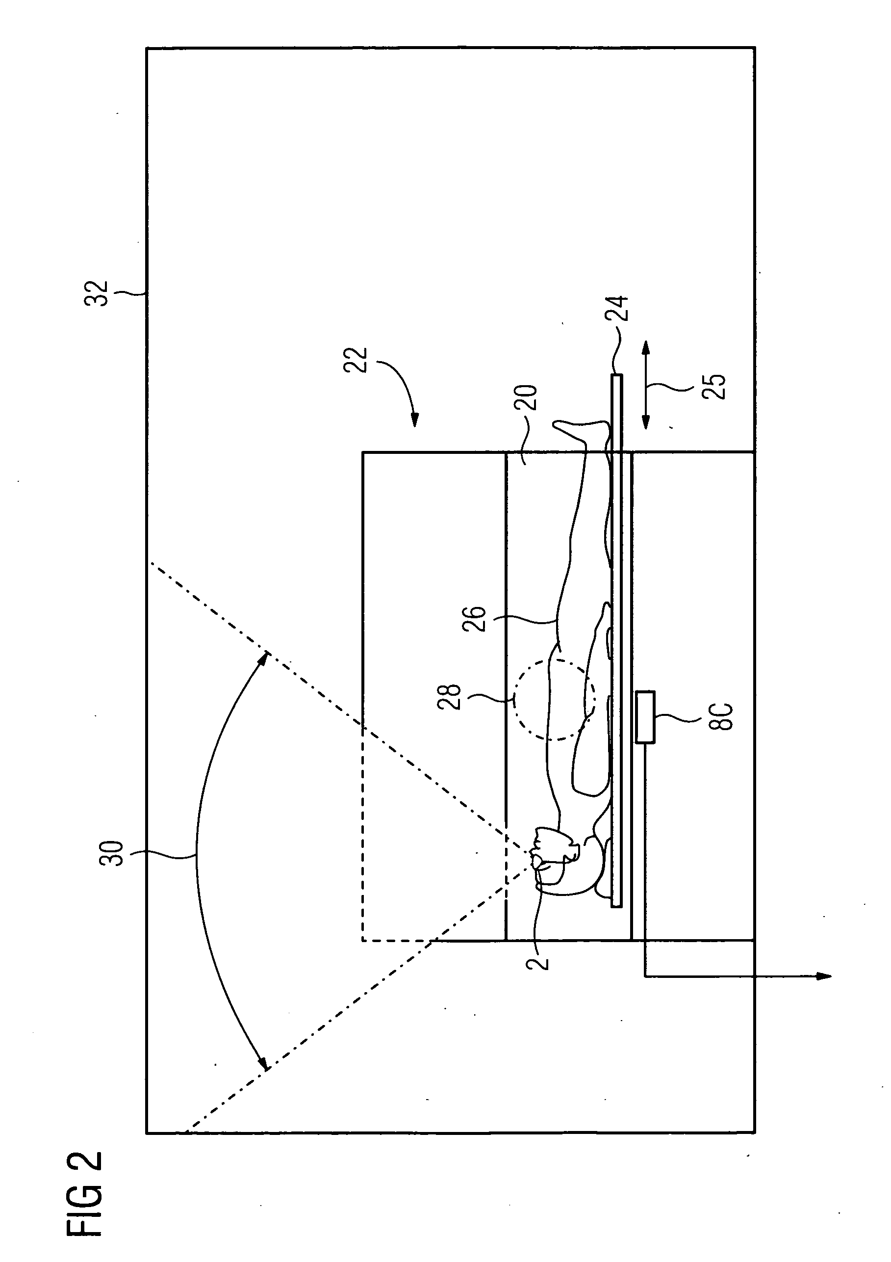
[0014]In a particularly advantageous embodiment the head position sensor is associated with a patient couch position detector. This means that a particularly simple realization for detecting the head position is produced thereby since, from the position of the patient couch, the position of the head in the longitudinal direction of the magnetic resonance device is also known.
[0015]A further particularly advantageous embodiment is distinguished by the fact that the head position sensor comprises magnetic field sensors. In this way, tilting of the head can be detected easily. The magnetic field required for determining the position and orientation is produced through a targeted or, in any case, necessary triggering of the gradient system to produce magnetic gradient fields. From the measurement signals, the position and orientation of the video eyeglasses is determined accordingly.

Problems solved by technology

Whilst recording magnetic resonance images a significant amount of cooperation is required from the patient and during the recording of images a high level of noise is produced from the switched gradient fields in interaction with the constant magnetic field which is an additional significant nuisance for the patient.
In addition there is the risk that the patient becomes claustrophobic due to the narrow interior and because he is generally required to lie on his back in the magnetic resonance device.
The unpleasant feelings experienced by the patient are additionally made worse if a special head antenna is used for head examinations which surrounds the patient's head relatively tightly even in the field of vision.
The optical trick is certainly a little strange because the patient looks upward and then sees his feet.
The disadvantage exists here that the patient is disturbed by the video sequences that appear on the display.
He may feel additionally insecure because he can no longer see anything that is going on outside.

Method used


Image

  • MR-compatible video system
  • MR-compatible video system
  • MR-compatible video system

Examples


Embodiment Construction

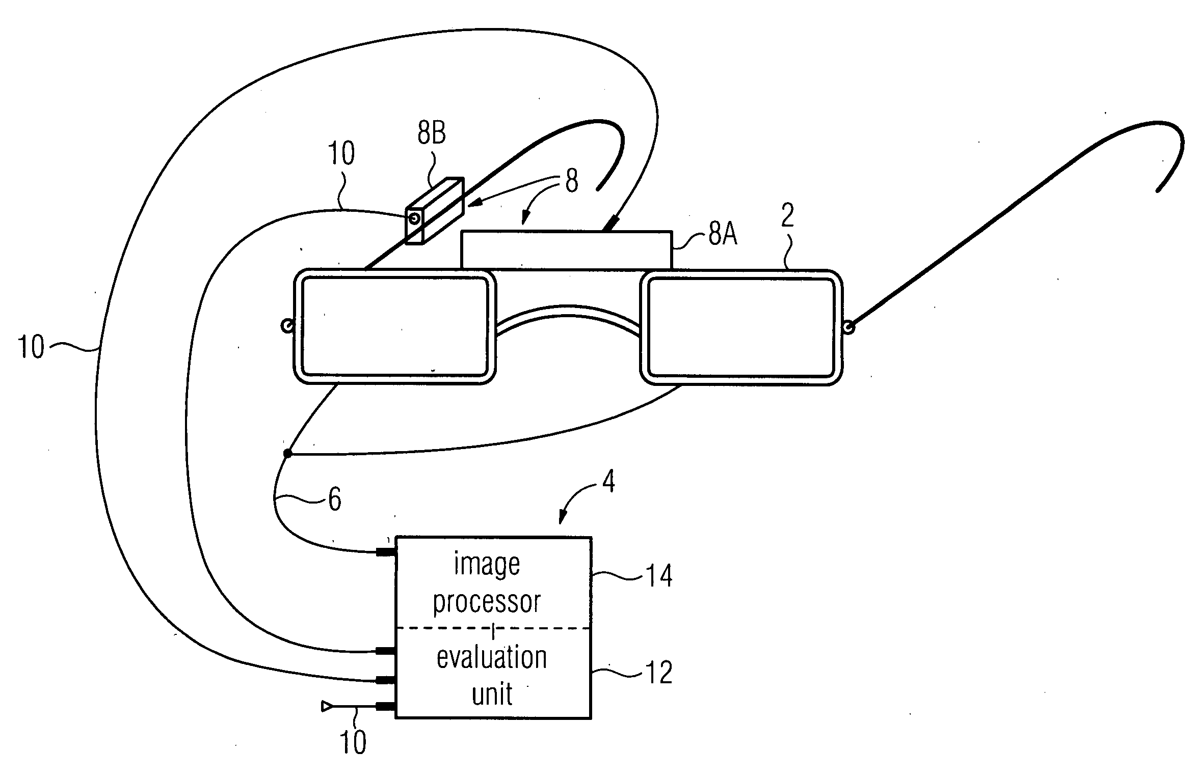
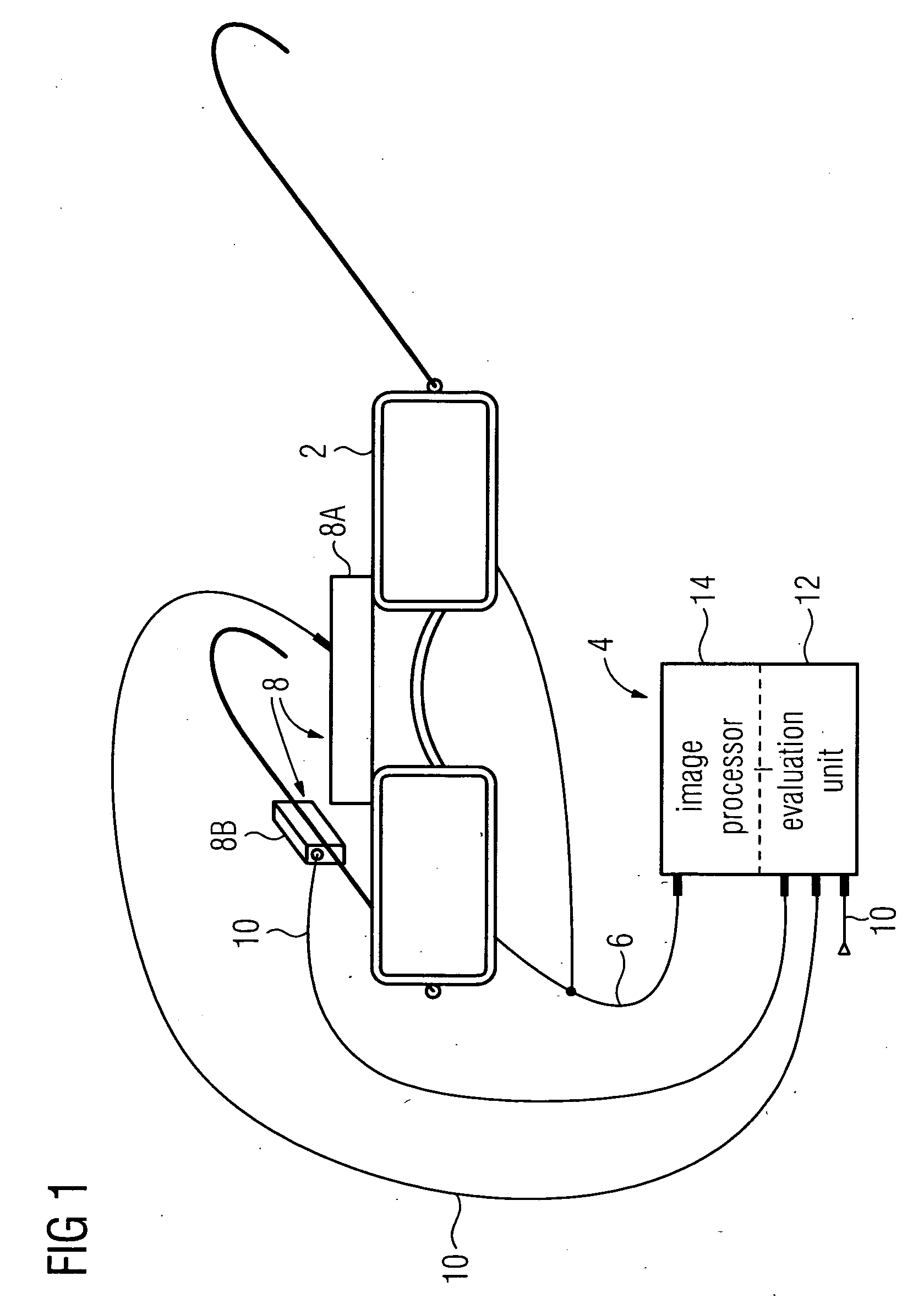
[0019]The MR-compatible video system illustrated schematically in FIG. 1 comprises MR-compatible video eyeglasses 2. As already explained in the introduction, such video eyeglasses 2 are available on the market, for example from the company Resonance Technology Inc. in Northridge, USA. The MR-compatible design of the video eyeglasses 2 means that no interference of magnetic resonance imaging is created by the video eyeglasses 2 and that similarly, the magnetic fields and high-frequency fields used in the magnetic resonance device do not interfere with the operation of the video eyeglasses 2. The use of non-magnetic materials and electric shielding of the electric components are significant measures for ensuring MR-compatibility.

[0020]The MR-compatible video eyeglasses 2 are connected to a graphics unit 4. The image signals are produced in the graphics unit 4, which are then fed to the MR-compatible eyeglasses 2 with the aid of an MR-compatible signal link 6. Both electrically shield...


PUM


Abstract

In an MR-compatible video system, MR-compatible video eyeglasses are connected to a graphics unit. A position sensor arrangement is connected to the graphics unit to detect the position and / or orientation of the MR-compatible video eyeglasses and / or the position of the pupils of a user. The graphics unit comprises means for producing image signals for MR-compatible video eyeglasses depending on the position and / or orientation of the MR-compatible video eyeglasses and / or the position of the pupils of the user.

Description

CROSS REFERENCE TO RELATED APPLICATIONS[0001]This application claims priority of German application No. 10 2007 030 972.6 filed Jul. 4, 2007, which is incorporated by reference herein in its entirety.FIELD OF THE INVENTION[0002]The invention relates to an MR-compatible video system with MR-compatible video eyeglasses.BACKGROUND OF THE INVENTION[0003]Magnetic resonance imaging (MR imaging) is used in medical diagnostics to create image data of a layer or an area from inside a human or animal body. In MR imaging a strong and uniform static magnetic field of 0.2 to 3 Tesla in size or greater is required. Such magnetic fields, in particular with high field strengths from 1 Tesla, are produced by superconducting magnets. Usually the superconducting magnet is of hollow cylindrical design, a cylindrical patient tunnel being embodied inside the hollow cylinder. Also arranged in the hollow cylindrical interior of the superconducting magnet are gradient coils for position encoding of the magn...

Claims


Application Information

Patent Timeline
IPC IPC(8): G06K9/00
CPCA61B5/742G01R33/283G01R33/288G06F3/013G02B2027/0187G06F3/012G02B27/017
Inventor SCHNELL, WILFRIEDTHESEN, STEFAN
Owner SIEMENS AG
Learn More