Composite sensor

a sensor and composite technology, applied in the field of composite sensors, can solve problems such as detection accuracy deterioration, and achieve the effects of preventing detection accuracy deterioration, increasing the moment of inertia moment, and preventing angular velocity detection accuracy deterioration

Active Publication Date: 2009-01-15
PANASONIC CORP
View PDF9 Cites 12 Cited by
  • Summary
  • Abstract
  • Description
  • Claims
  • Application Information

AI Technical Summary

Benefits of technology

[0010]A composite sensor according to an aspect of the present invention includes an angular velocity sensor element, an acceleration sensor element, a signal processing IC for processing signals from the angular velocity sensor element and the acceleration sensor element, an inner package for accommodating the angular velocity sensor element, the acceleration sensor element, and the signal processing IC, a coupler that is connected to the inner package and that is elastically-deformable, and a fixing member connected to the coupler for holding the inner package via the coupler. The composite sensor has a structure in which one of the acceleration sensor element and the signal processing IC is located at the right side with respect to the center of the inner package and the other of the acceleration sensor element and the signal processing IC is located at the left with respect to the center of the inner package. This structure thus separates such heavy components to the left and right in the inner package. This structure increases the moment of inertia moment while positioning the center of gravity of the inner package at the center of the inner package. This arrangement prevents the package from rotating around the center axis of the inner package. This prevents a noise component from being mixed in a detection signal of an angular velocity, thus preventing the angular velocity from having detection accuracy deteriorate.
[0011]A composite sensor according to another aspect of the present invention includes the coupler made of material elastically deforming to deflect. The angular velocity sensor element vibrates to produce a Coriolis force to detect an angular velocity. The angular velocity sensor element vibrates in a direction perpendicular to a direction along which the coupler deflects. A detection direction of the acceleration sensor element is parallel to the direction along which the angular velocity sensor element vibrates. In this structure, the acceleration sensor element has a detection axis perpendicular to the direction along which the coupler deflects. Since the coupler deflects little in directions perpendicular to the direction along which the coupler deflects, an acceleration applied to the composite sensor is substantially transmitted directly to the acceleration sensor element, thus preventing detection accuracy from deteriorating.
[0012]A composite sensor according to still another aspect of the present invention includes the angular velocity sensor element and the acceleration sensor element which are inclined in the inner package. This arrangement allows the angular velocity sensor element to have a detection axis in the vertical direction and allows the acceleration sensor element to have a detection axis in a direction along which the vehicle proceeds even when a device having the composite sensor mounted therein is inclined to be mounted in a vehicle, thereby maintaining detection accuracy.

Problems solved by technology

If a damper is not mounted to the case, vibration and impact are applied to the angular velocity sensor element directly from outside, and disturb predetermined vibration of the angular velocity sensor, accordingly causing detection accuracy to deteriorate.

Method used


Image

  • Composite sensor
  • Composite sensor
  • Composite sensor

Examples


exemplary embodiment 1

[0026]Exemplary Embodiment 1 of the present invention will be described below.

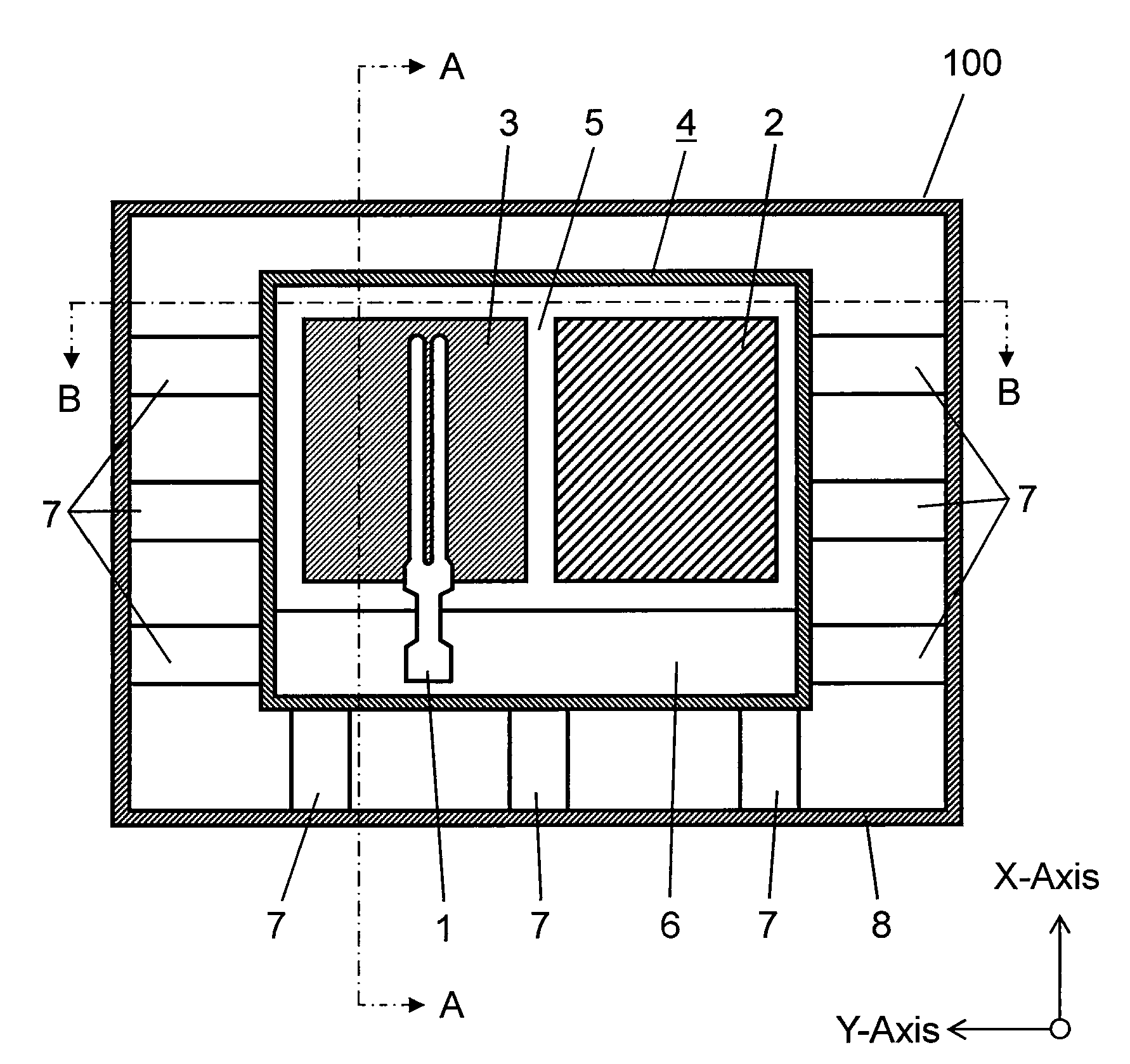
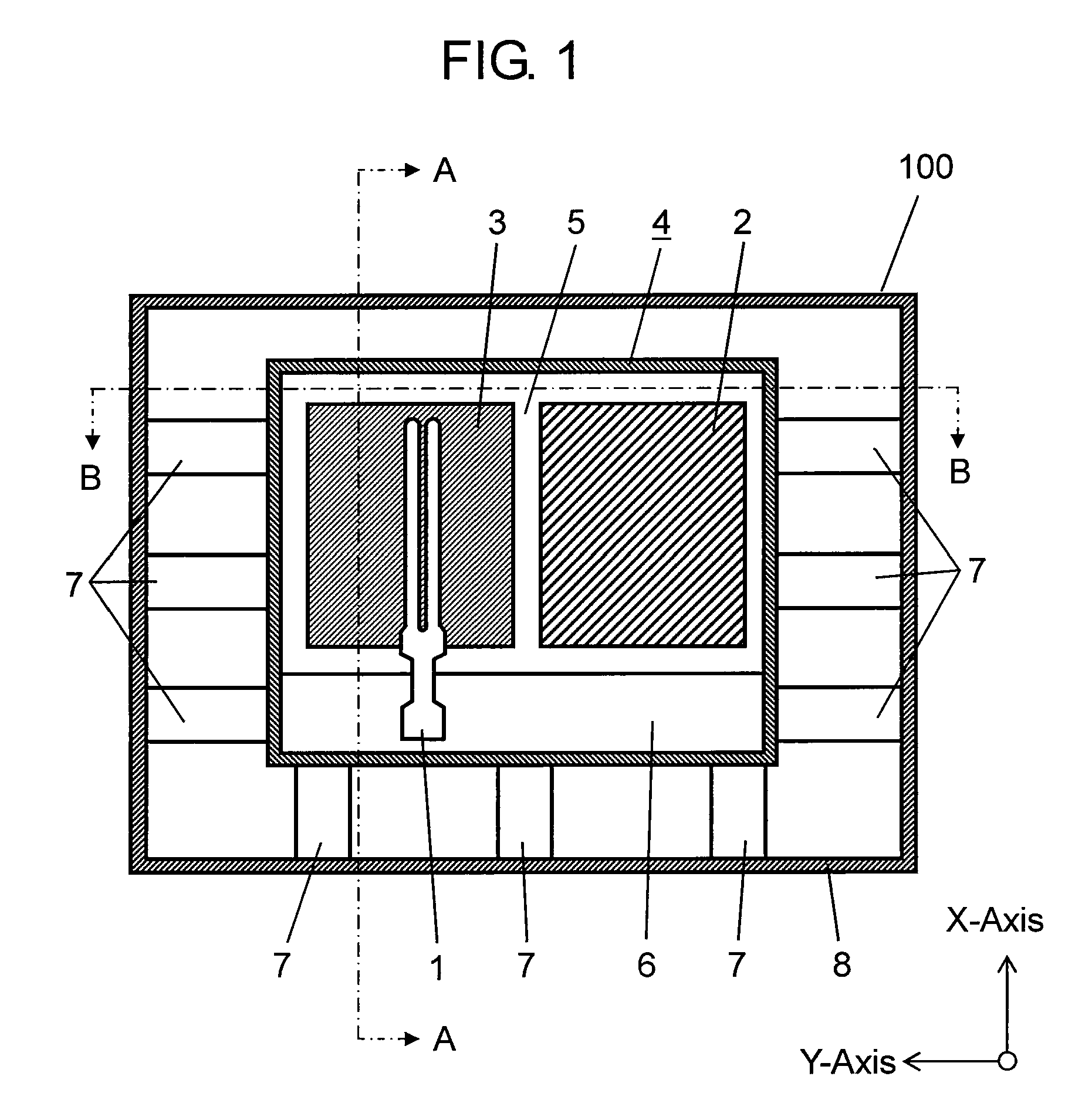
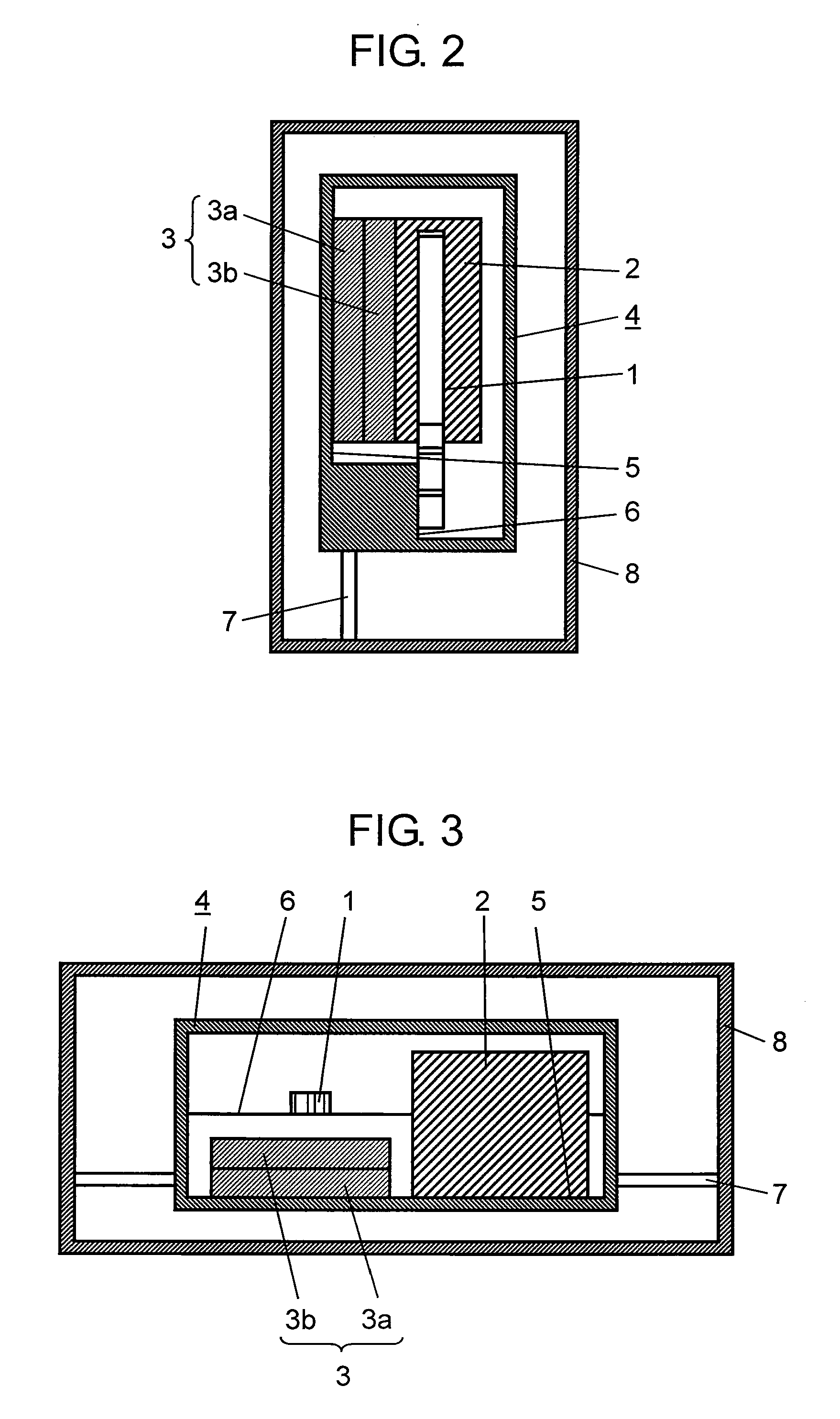
[0027]FIG. 1 is a cross-sectional view of composite sensor 100 according to Embodiment 1 of the invention. FIG. 2 is a cross-sectional view of the sensor at line A-A shown in FIG. 1. FIG. 3 is a cross-sectional view of the cross section at line B-B shown in FIG. 1.

[0028]As shown in FIGS. 1 to 3, composite sensor 100 includes angular velocity sensor element 1 having a tuning fork shape, acceleration sensor element 2 having a substantially rectangular parallelepiped shape, and signal processing IC 3 for processing signals from angular velocity sensor element 1 and acceleration sensor element 2. Signal processing IC 3 includes first IC section 3a as one IC and second IC section 3b as another other IC stacked on the first IC section.

[0029]Angular velocity sensor element 1, acceleration sensor element 2, and signal processing IC 3 are accommodated in inner package 4. Signal processing IC 3 is mounted to a porti...

exemplary embodiment 2

[0044]Exemplary Embodiment 2 of the present invention will be described below.

[0045]FIG. 7 is a plane section view of a composite sensor according to Embodiment 2 of the invention. In FIG. 7, constituents identical to those of Embodiment are denoted by the same reference numerals, and their description will be omitted. In FIG. 7, the X-axis and the Y-axis are perpendicular to each other.

[0046]The composite sensor according to Embodiment 2 of the invention is different from the composite sensor according to Embodiment 1 in that angular velocity sensor element 1 and acceleration sensor element 2 are inclined in inner package 4, and coupler 7 has an S-shape.

[0047]When the composite sensor according to Embodiment 2, different from the composite sensor according to Embodiment, the X-axis and the Y-axis incline, and both of angular velocity sensor element 1 and angular velocity sensor element 2 have inclined detection axes. This structure improves detection accuracy when the composite sen...


PUM


Abstract

A composite sensor includes an angular velocity sensor element, an acceleration sensor element, a signal processing IC for processing signals from the angular velocity sensor element and the acceleration sensor element, an inner package for accommodating the angular velocity sensor element, the acceleration sensor element, and the signal processing IC; a coupler connected to this inner package, and a fixing member connected to this coupler for holding the inner package via this coupler. The coupler is elastically deformable. One of the acceleration sensor element and the signal processing IC is located at the right with respect to the center of the inner package, and the other of the acceleration sensor element and the signal processing IC is located at the left with respect to the center of the inner package. The composite sensor angular maintains its characteristics of the angular velocity sensor element while the angular velocity sensor element and the acceleration sensor element are accommodated in one package.

Description

TECHNICAL FIELD[0001]The present invention relates to a composite sensor for detecting an angular velocity and an acceleration mainly used in a navigation system for a vehicle, such as an automobile, various controls of a vehicle, or a shaking detector of a camera.BACKGROUND ART[0002]A composite sensor including an angular velocity sensor element and an acceleration sensor element which are accommodated in one package is known (Patent Document 1).[0003]A sensor to be angled to be mounted in a vehicle is known. This sensor has a detection axis coinciding with a vertical direction while being mounted in the vehicle. (Patent Document 2).[0004]An acceleration sensor including an acceleration sensor element which includes a mass portion having a weight and an elastically-deformable portion having an end fixed is known. The mass portion has a thickness different from that of the deformable portion, hence causing the center of gravity to deviate from a plane parallel to the deformable port...

Claims


Application Information

Patent Timeline
Patent Type & Authority Applications(United States)
IPC IPC(8): G01C19/56G01C19/5628G01P15/08
CPCG01P1/023G01C19/56
Inventor OHKOSHI, HIDEO
Owner PANASONIC CORP
Why Eureka
Try Eureka