Supercharge Your Innovation With Domain-Expert AI Agents!

Inner structure of filler neck of fuel filler tube

a technology inner structure, which is applied in the directions of liquid handling, packaging goods, transportation and packaging, etc., can solve the problems of complicated construction of fuel filler tube b>261/b>, and achieve the effect of simple construction and stable fuel flow

Active Publication Date: 2009-01-15
HONDA MOTOR CO LTD
View PDF5 Cites 11 Cited by
  • Summary
  • Abstract
  • Description
  • Claims
  • Application Information

AI Technical Summary

Benefits of technology

[0009]In view of the foregoing prior art problems, it is an object of the present invention to provide an improved inner structure of a filler neck of a fuel filler tube which permits a stable flow of fuel irrespective of possible variation in inserted amount of the fuel filling gun, and yet can be simplified in construction.
[0011]Because the pipe constituting the nozzle support section has the inner diameter substantially equal to the outer diameter of the nozzle, the distal end, located remotely from the filling port and orientated toward the fuel tank, of the pipe (nozzle support section) functions similarly to the distal end of the nozzle of the fuel filling gun. Thus, irrespective of possible variation in the inserted amount of the nozzle in the filler neck, the fuel can always start jetting out from the nozzle into the fuel filler tube at the same position, and thus, the fuel flow in the filler tube can be stabilized. Further, because the pipe has the inner diameter substantially equal to the outer diameter of the nozzle, the overall construction of the inner structure of the filler neck can be significantly simplified by forming the pipe, for example, as a straight pipe.
[0013]In an embodiment, the pipe has a reduced inner diameter at its distal end located remote from the filling port, and the reduced inner diameter substantially equals the inner diameter of the nozzle. With the reduced inner diameter substantially equal to the inner diameter of the nozzle, the distal end of the pipe (nozzle support section) functions similarly to the distal end of the nozzle of the fuel filling gun. Thus, irrespective of possible variation in the inserted amount of the nozzle in the filler neck, the fuel can always start jetting out from the nozzle into the fuel filler tube at the same position, and thus, the fuel flow in the filler tube can be stabilized.
[0014]In an embodiment, the pipe has a distal end portion remote from the filling port. The distal end portion extends, in a direction toward the fuel tank, to a position within a length range of an intermediate bent section of the fuel filler tube, or to a position beyond the length range of the intermediate bent section. Such an arrangement can prevent undesired scattering of the fuel within the intermediate bent section of the fuel filler tube.

Problems solved by technology

However, the fuel filler tube 261 is complicated in construction because the small-diameter tube 265 needs to be provided within the large-diameter tube 267.

Method used


Image

  • Inner structure of filler neck of fuel filler tube
  • Inner structure of filler neck of fuel filler tube
  • Inner structure of filler neck of fuel filler tube

Examples


first embodiment

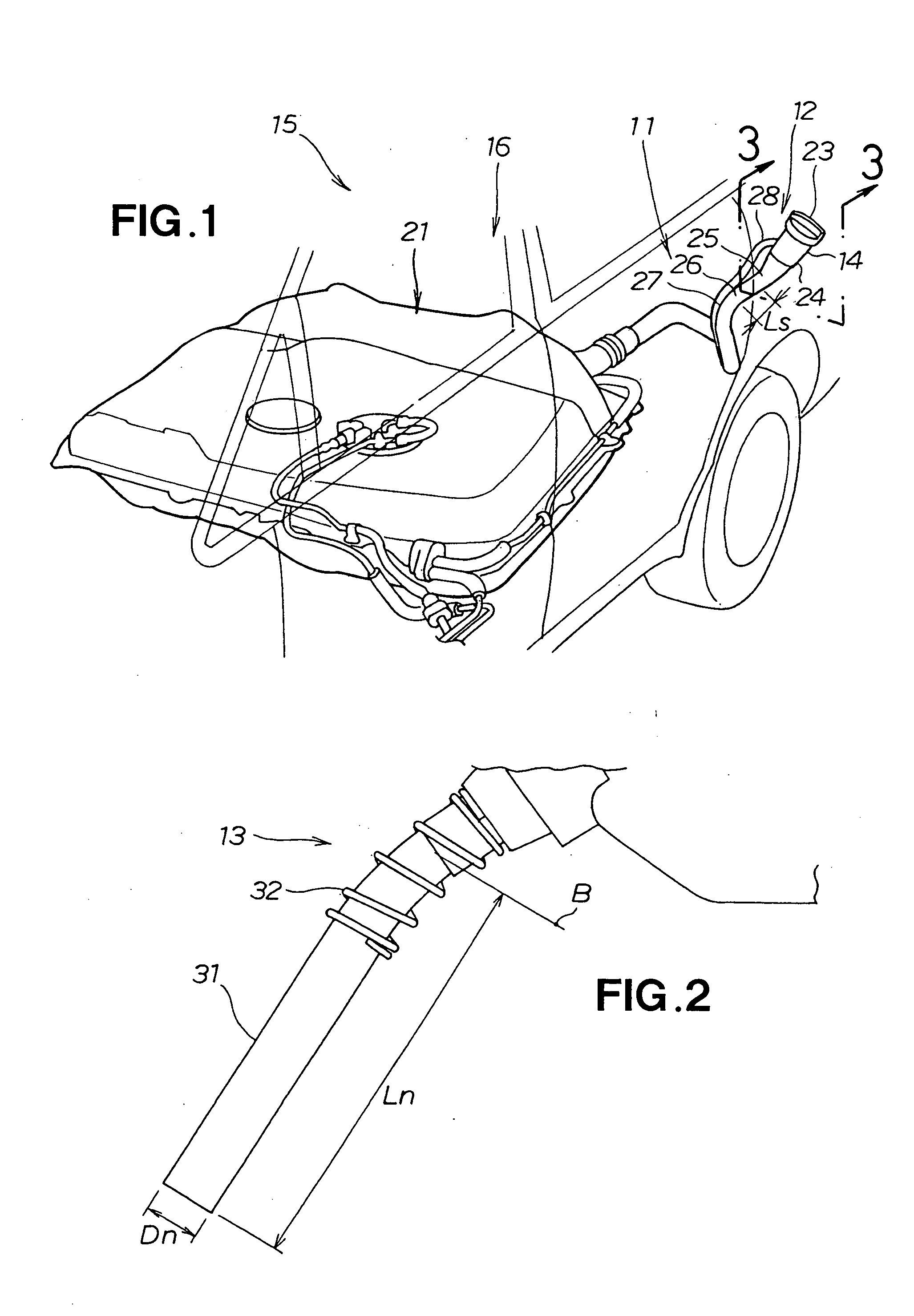
[0028]Reference is now made to FIG. 1 showing in perspective an inner structure of a filler neck 12 (hereinafter also referred to as “filler neck structure 12” for convenience of description) in a fuel filler tube provided in a vehicle. The filler neck structure 12 is provided within the fuel filler tube 11 adjacent to the inner or lower end of a filling port 14 of the vehicle in which a fuel filling gun 13 (see FIG. 2) is insertable when fueling, as will be detailed later. The filler neck structure 12 is employed in a fuel storage apparatus 16 of the vehicle 15.

[0029]The fuel storage apparatus 16 includes a fuel tank 21 disposed under a rear seat of the vehicle 15, and the fuel filler tube 11 leading to and communicating with the fuel tank 21.

[0030]In the fuel filler tube 11, a cap 23 is removably fitted on the filling port 14, and a first tube section 24 is provided in a relatively upright posture and integrally connected with the lower end of the filling port 14. The fuel filler ...

second embodiment

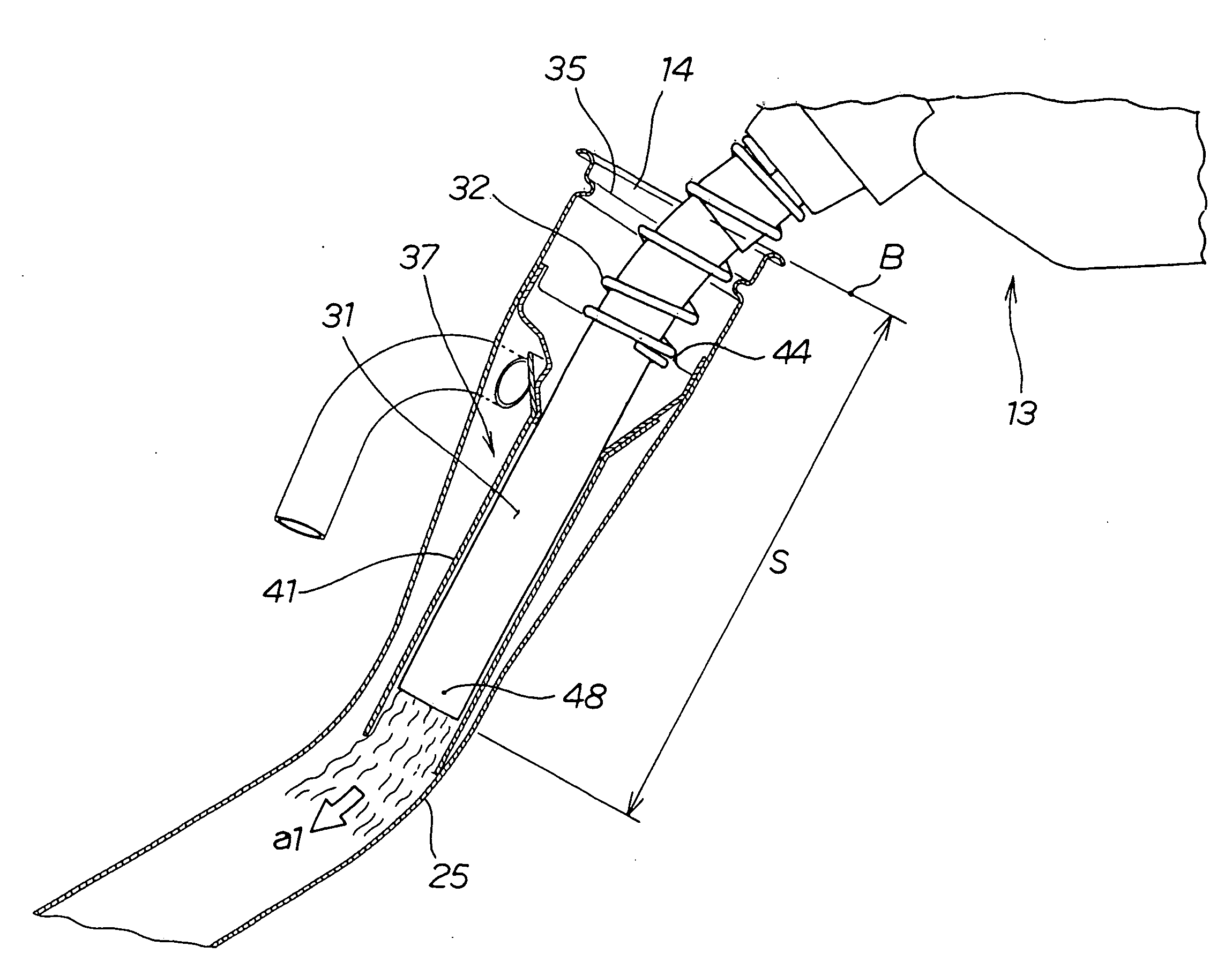
[0054]the filler neck structure 12B is characterized by including a novel nozzle support portion 37B provided in the filling port 14. The nozzle support portion 37B includes the pipe member 41B. The pipe member 41B has the axis line Cp offset from the axis line C1 of the fuel filler tube 11 by an amount Y2 in the Y-axis direction and by an amount X1 in the X-axis direction (as indicated by arrow b1) so that a swirling flow can be produced in the fuel.

[0055]It should be appreciated that the offset directions and offset amounts of the pipe member 41B may be chosen as desired without being limited to the aforementioned.

[0056]The second embodiment of the filler neck structure 12B can accomplish substantially the same advantageous benefits as the first embodiment of the inner structure 12.

[0057]Further, in the second embodiment of the filler neck structure 12B, the outlet end (or distal end) portion 48 of the pipe member 41, oriented inwardly away from the filling port 14, is offset from...

third embodiment

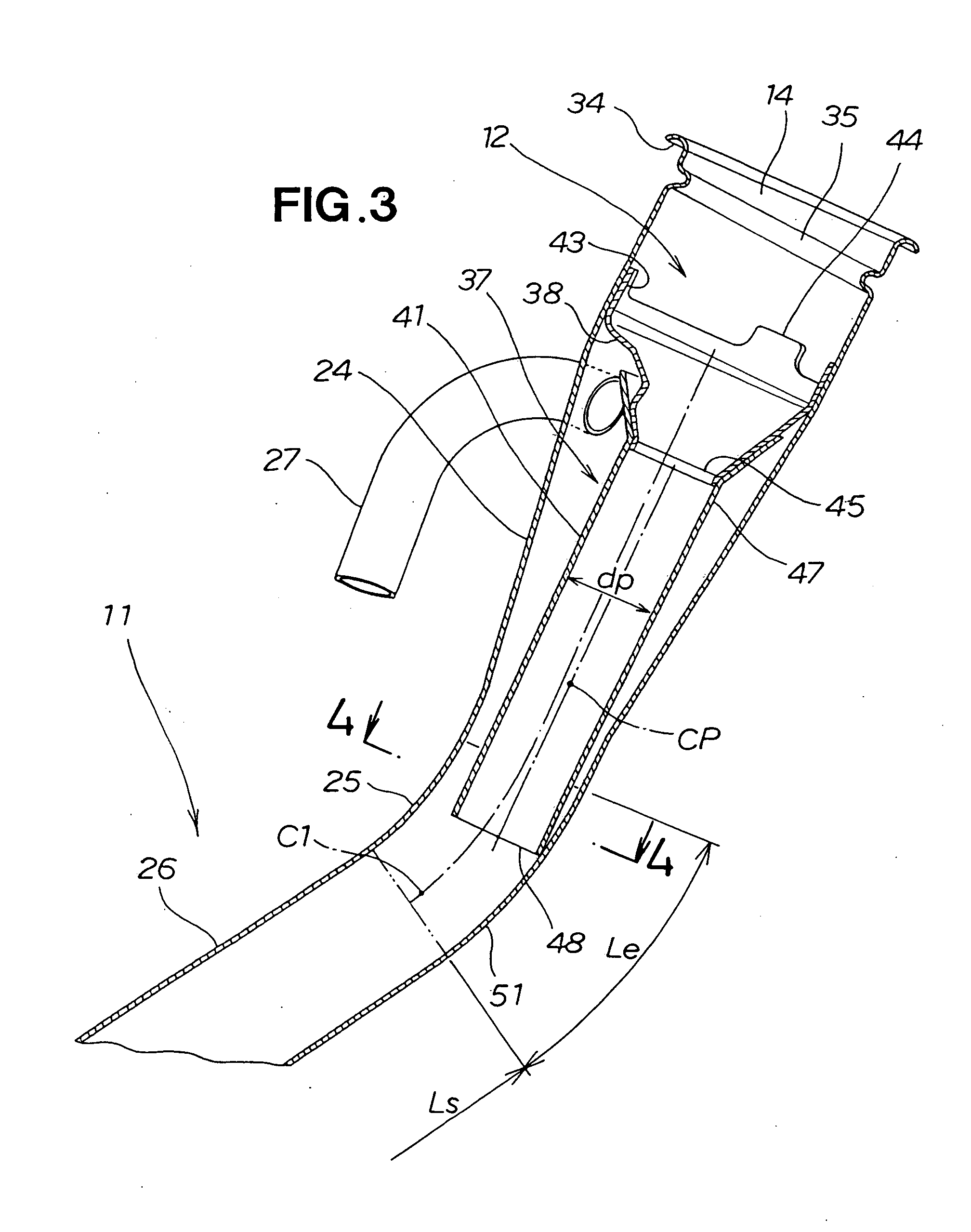
[0060]the filler neck structure 12C is characterized by including a novel nozzle support portion 37C provided in the filling port 14. The nozzle support portion 37C includes the nozzle bracket 38C, and the pipe member 41C fixed to the pipe-connecting end portion 45C of the nozzle bracket 38C.

[0061]The pipe member 41C, which has a substantial conical shape, has a gradually-decreasing inner diameter dp so that the pipe member 41C has, at the outlet end (or distal end) portion 48, a reduced inner diameter dp substantially equals the inner diameter of the nozzle 31 of the fuel filling gun 13.

[0062]The third embodiment of the filler neck structure 12C can accomplish substantially the same advantageous benefits as the first embodiment of the inner structure 12.

[0063]Whereas the embodiments of the filler neck structure of the present invention have been described above as employed in a vehicle to be fueled via a fuel filling gun, the basic principles of the of the present invention may be ...


PUM

PropertyMeasurementUnit
Lengthaaaaaaaaaa
Angleaaaaaaaaaa
Diameteraaaaaaaaaa

Abstract

In an inner structure of a filler neck of a fuel filler tube, a nozzle support section for supporting a nozzle of a fuel filling gun at a gas station includes a pipe member having an inner diameter substantially equal to the outer diameter of the nozzle, and the nozzle is inserted in the pipe member when fueling. Fuel emitted from the nozzle is directed through the pipe member to an outlet end (distal end) of the nozzle support section, at which it starts flowing along an intermediate bent section of the filler tube. Thus, even when the fuel filling gun is not sufficiently inserted in the filler neck, i.e. inserted short of a standard inserted amount, the fuel is allowed to properly jet out in the bent section just as when the fuel filling gun is sufficiently inserted in the filler neck up to the standard inserted amount.

Description

FIELD OF THE INVENTION[0001]The present invention relates to an improved inner structure of a filler neck of a fuel filler tube in which a fuel filling gun is inserted at a gas station for fueling a vehicle.BACKGROUND OF THE INVENTION[0002]Generally, automotive vehicles (hereinafter referred to simply as “vehicles”) have, in their rear side surface, a filling port for supplying fuel into the vehicle. In some automotive vehicles, a direction regulating member is provided inside the interior of the filling port for regulating a flow direction of the fuel emitted from a fuel filling gun (see, for example, Japanese Patent Publication No. 3,578,421, which will hereinafter be referred to as “Patent Document 1”). Further, in some vehicles, a position regulating structure is provided inside the filling port for regulating an inserted position of the fuel filling gun (see, for example, Japanese Patent Publication No. 3,616,516, which will hereinafter be referred to as “Patent Document 2”). A...

Claims


Application Information

Patent Timeline
IPC IPC(8): B60K15/04
CPCB60K15/04
Inventor KOBAYASHI, KAZUHIROMURABAYASHI, SHINYAUTSUMI, YUTAKAOHISHI, TAKESHI
Owner HONDA MOTOR CO LTD
Features
  • R&D
  • Intellectual Property
  • Life Sciences
  • Materials
  • Tech Scout
  • Unparalleled Data Quality
  • Higher Quality Content
  • 60% Fewer Hallucinations
Learn More