Counter-stream-mode oscillating-flow heat transport apparatus

a heat transport apparatus and counter-stream mode technology, applied in lighting and heating apparatus, semiconductor/solid-state device details, laminated elements, etc., to achieve the effect of improving heat transport capability, reducing cost, and reducing manufacturing efficiency

Inactive Publication Date: 2009-01-15
DENSO CORP
View PDF30 Cites 3 Cited by
  • Summary
  • Abstract
  • Description
  • Claims
  • Application Information

AI Technical Summary

Benefits of technology

[0017]The present invention was developed in view of the aforementioned problems. It is therefore a first object of the invention to provide a new counter-stream-mode oscillating-flow heat transport apparatus that improves heat transport capability when compared with the prior art. A second object is to provide a counter-stream-mode oscillating-flow heat transport apparatus that is capable of being manufactured more efficiently and at a lower cost than the prior art.

Problems solved by technology

In contrast to this, the prior art counter-stream-mode oscillating-flow heat transport apparatus does not provide oscillatory movements in a manner such that the fluid would collide against the heat source (5) at the portion of the flow paths corresponding to the heat-generating element, thus essentially providing no turbulent effect and a lower coefficient of heat transfer than this embodiment.

Method used


Image

  • Counter-stream-mode oscillating-flow heat transport apparatus
  • Counter-stream-mode oscillating-flow heat transport apparatus
  • Counter-stream-mode oscillating-flow heat transport apparatus

Examples


seventh embodiment

[0189]In the fourteenth embodiment, to impart oscillatory displacements to the fluid in a manner such that the fluid located near the heat-generating element 5 be directed toward the heat-generating element 5, a portion of the flow paths 3 adjacent to the heat-generating element 5 is disposed generally perpendicular to the plate surface 5a of the heat-generating element 5 with the other portions being disposed generally parallel to the plate surface 5a of the heat-generating element 5. As shown in FIGS. 14A through 15, this embodiment is configured such that the other portions are also disposed generally perpendicular to the plate surface 5a of the heat-generating element 5 in addition to the portion of the flow paths 3 adjacent to the heat-generating element 5.

[0190]In FIGS. 14A to 14C, since the heat-radiating portion 4 is larger than the portion to which the heat-generating element 5 is attached, an increased angle of inclination is provided relative to the normal direction of th...

eighth embodiment

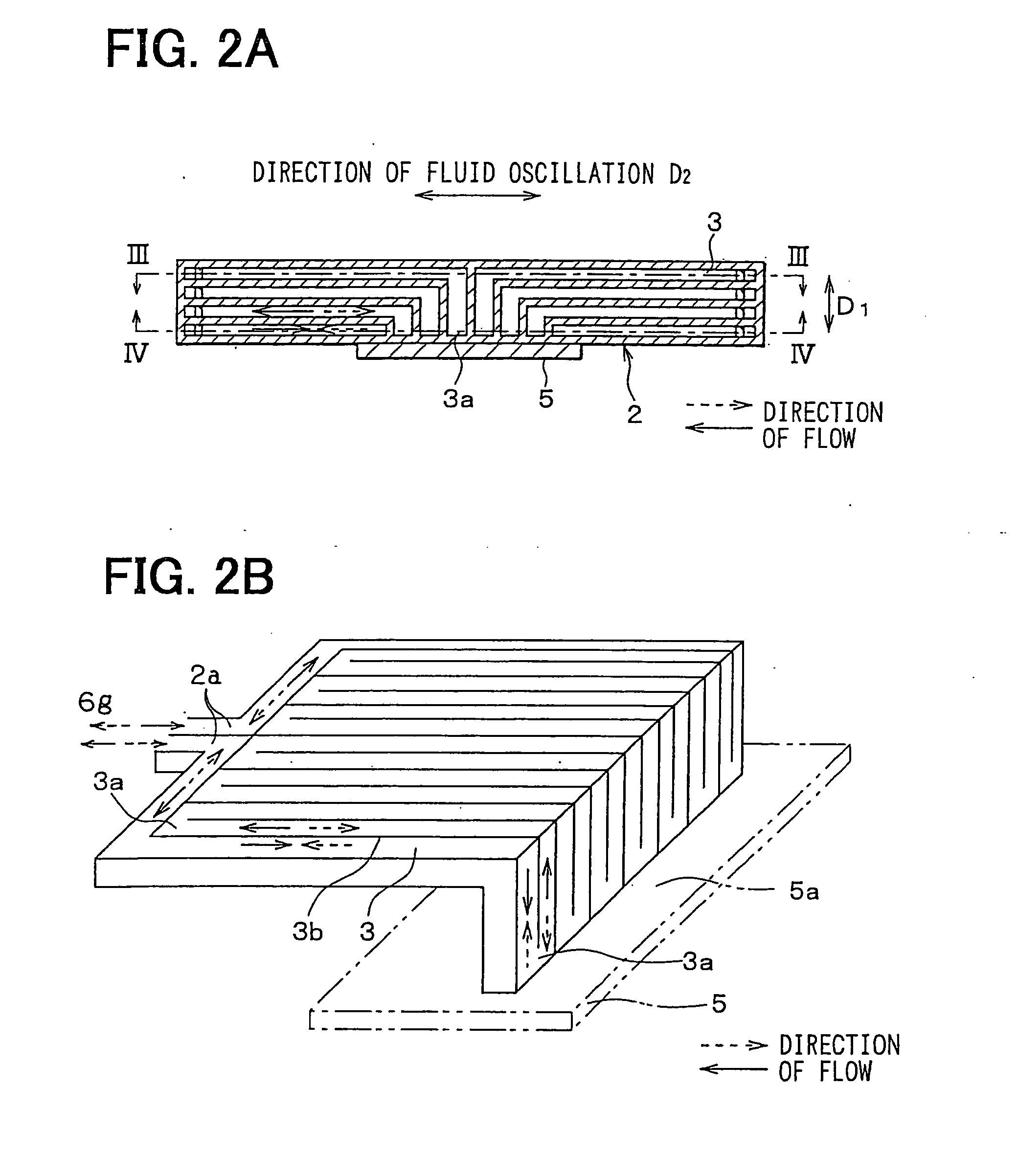
[0192]In the aforementioned embodiments, heat is exchanged between adjacent flow paths 3 on a plane parallel to the plate surface 5a. However, as shown in FIGS. 16A and 16B, this embodiment allows heat to be exchanged between adjacent flow paths 3 on a plane orthogonal to the plate surface 5a, thereby providing an increased area contributing to heat exchange.

[0193]Furthermore, in the aforementioned embodiments, the fluids in adjacent flow paths 3 are oscillated in the counterflow directions parallel to each other on a plane parallel to the plate surface 5a. However, in this embodiment, the fluids in adjacent flow paths 3 are oscillated in crosswise directions on a plane orthogonal to the plate surface 5a.

[0194]The fluids in adjacent flow paths 3 on a plane orthogonal to the plate surface 5a may be oscillated for heat exchange in the crosswise directions, while the fluids in the adjacent flow paths 3 on a plane parallel to the plate surface 5a may be oscillated in the counterflow di...

ninth embodiment

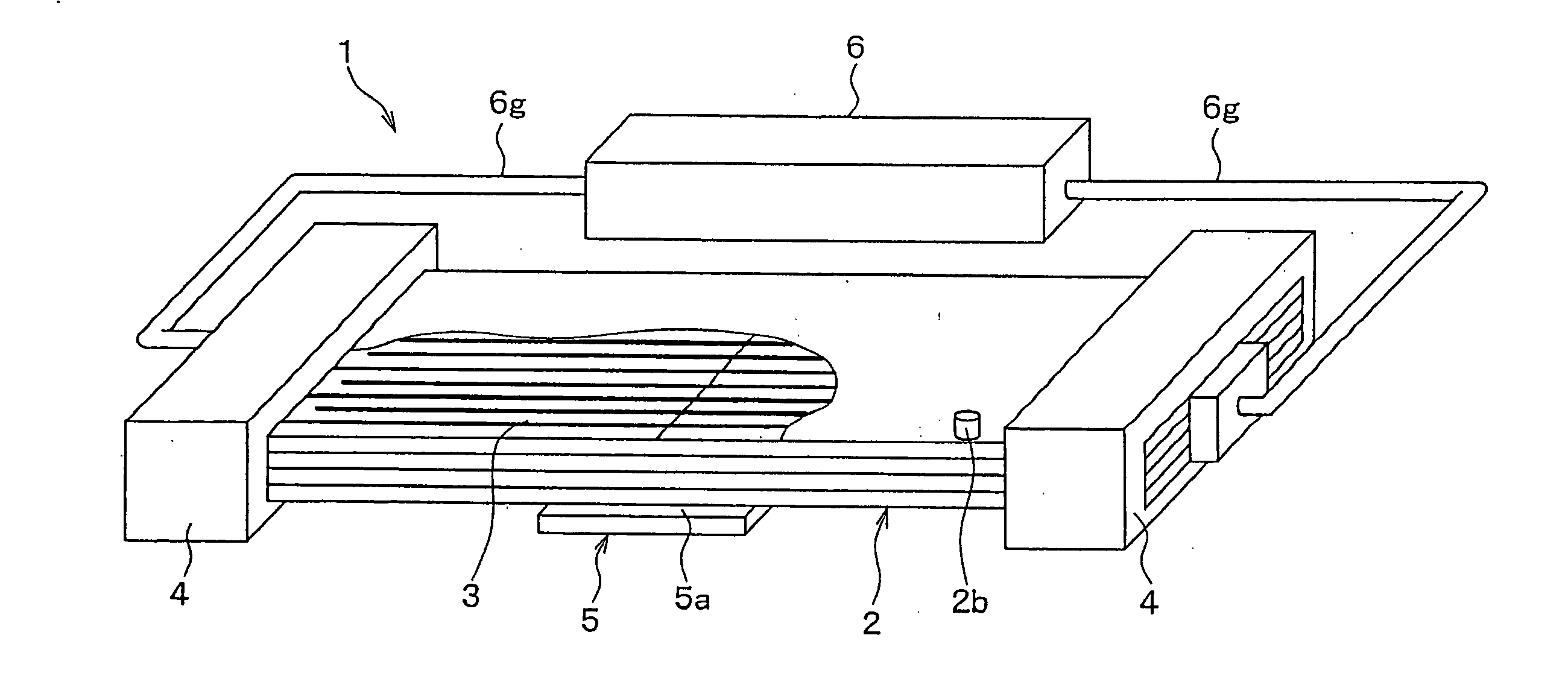
[0196]In the aforementioned embodiments, the heat transport device assembly 2 is nearly a perfect rigid body. However, as shown in FIG. 17, this embodiment is provided with a bounding portion 3b, among the members constituting the flow paths 3, formed of a metal such as an annealed copper having good thermal conductivity. Additionally, portions 3d, separate from the bounding portion 3b, are formed of a soft material such as resin. This resin portion 3d can be recessed to accept the metal thin plate 3b. This construction and these materials allows the heat transport device assembly 2 to be readily bent just like an electric cord, thereby facilitating the implementation of the counter-stream-mode oscillating-flow heat transport apparatus.


PUM


Abstract

A counter-stream-mode oscillating-flow heat transport apparatus improves heat transport capability by imparting oscillatory displacement to a fluid located near a heat-generating element such that the fluid is directed toward the heat-generating element. Turning portions of serpentine flow paths are disposed to face the heat-generating element. The flow paths are stacked in multiple layers in the direction from the heat-generating element to the flow paths, and a plurality of flow paths are disposed adjacent to the heat-generating element in the direction of fluid oscillation.

Description

CROSS REFERENCE TO RELATED APPLICATIONS[0001]This application is a continuation of U.S. patent application Ser. No. 11 / 472,255 filed Jun. 21, 2006, which is a divisional application of U.S. patent application Ser. No. 10 / 634,341 filed Aug. 5, 2003 which is based upon, claims the benefit of priority of, and incorporates by reference, the contents of Japanese Patent Applications No. 2002-229993 filed Aug. 7, 2002, No. 2003-67928 filed Mar. 13, 2003, and No. 2003-167657 filed Jun. 12, 2003.BACKGROUND OF THE INVENTION[0002]1. Field of the Invention[0003]The present invention relates to a counter-stream-mode oscillating-flow heat transport apparatus which creates oscillations of counterflow fluid mediums in adjacent flow paths and microchannels to thereby exchange heat between the adjacent flow paths and transport heat from a hot region to a cold region, the apparatus being effectively applicable to a thermally quasi-superconductive plate, a thermal switch, a thermal diode, and so forth....

Claims


Application Information

Patent Timeline
Patent Type & Authority Applications(United States)
IPC IPC(8): F28D1/00F28D15/06F28D15/02F28F3/12F28F13/10H01L23/473H05K7/20
CPCF28D2021/0029F28F3/12F28F13/10F28F2260/02H01L23/473H01L2924/0002H05K7/20272F28F2250/08H01L2924/00F28D15/02
Inventor NARA, KENICHIHAGIWARA, YASUMASAKOHARA, KIMIOYATSUZUKA, SHINICHIINOUE, SEIJIAKIMOTO, AKITOSUGIURA, MAKOTOKISHITA, KOUJISUZUKI, NOBUNAO
Owner DENSO CORP
Why Eureka
Try Eureka