Determining formation parameters using electromagnetic coupling components

Inactive Publication Date: 2009-01-15
SCHLUMBERGER TECH CORP
View PDF11 Cites 74 Cited by
  • Summary
  • Abstract
  • Description
  • Claims
  • Application Information

AI Technical Summary

Benefits of technology

[0017]A method to determine one or more parameters of a formation traversed by a borehole, at least a portion of the formation having substantially parallel boundaries, the method comprising disposing a tool in the borehole, wherein the tool includes a transmitter having a dipole moment at an angle θT with respect to a longitudinal axis of the tool and a receiver having a dipole moment at an angle θR with respect to the longitudinal axis of the tool, the transmitter and receiver comprising a transmitter-receiver pair; transmitting an electromagnetic signal while rotating the tool; receiving the electromagnetic signal to produce a measured signal

Problems solved by technology

However, this patent does not provide any details as to how the azimuthal resistivity can be obtained, nor does it describe any further boundary detection/characterization techniques requi

Method used


Image

  • Determining formation parameters using electromagnetic coupling components
  • Determining formation parameters using electromagnetic coupling components
  • Determining formation parameters using electromagnetic coupling components

Examples


Embodiment Construction

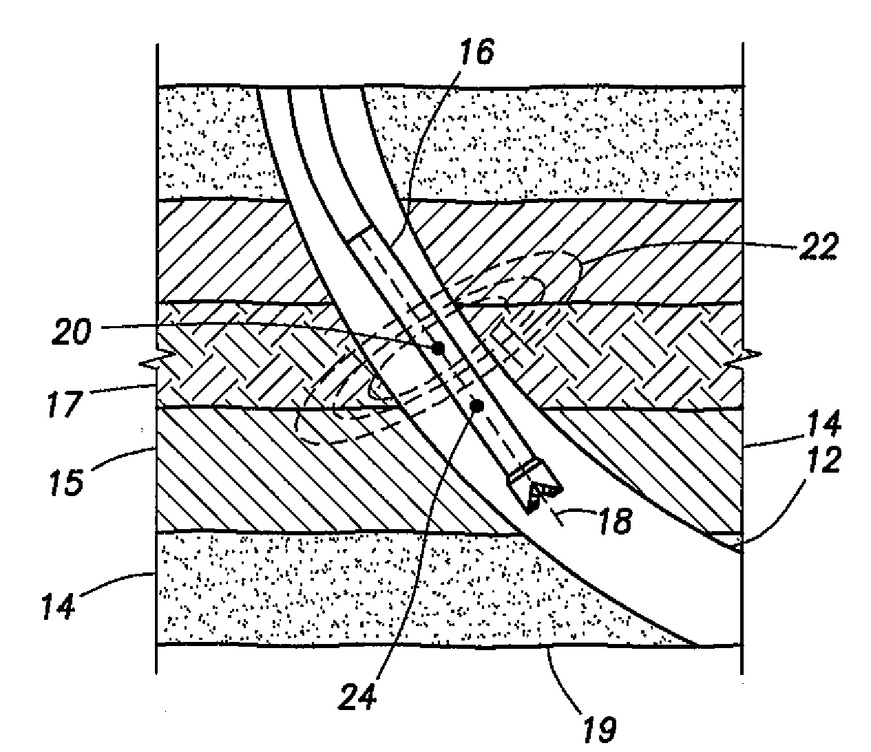
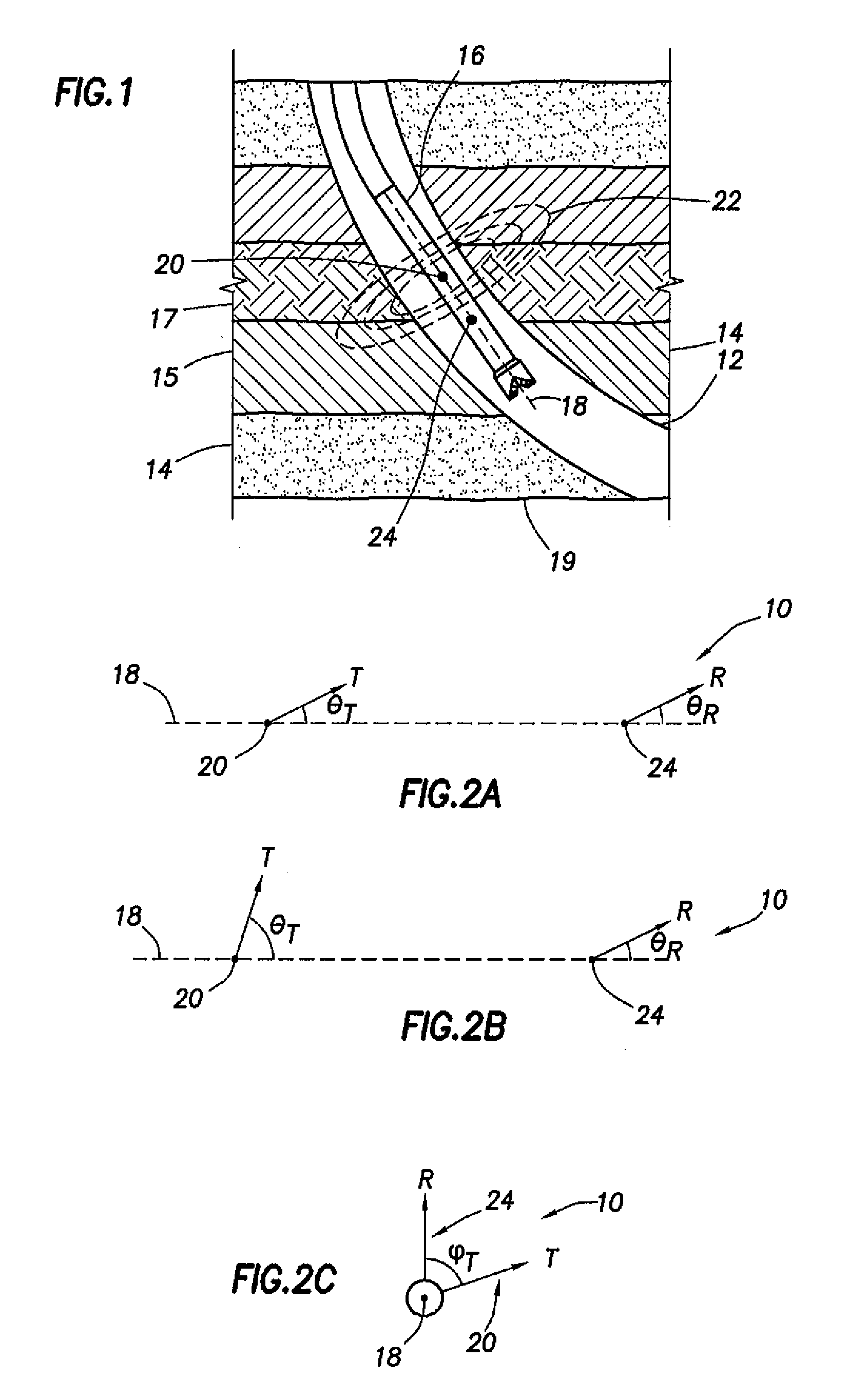
[0025]Refer now to the drawings wherein depicted elements are not necessarily shown to scale and wherein like or similar elements are designated by the same reference numeral through the several views.

[0026]As used herein, the terms “up” and “down”; “upper” and “lower”; and other like terms indicating relative positions to a given point or element are used to more clearly describe some elements of the embodiments of the invention. Commonly, these terms relate to a reference such that the surface from which drilling operations are initiated is the upper portion and the total depth of the well is the lower portion.

[0027]As used herein, the term “tool” may be used interchangeably to indicate, for example and without limitation, a wireline tool or a logging-while-drilling tool. One of ordinary skill in the art would know how to adapt a wireline tool, for example, to withstand and operate in the harsh environment of a logging-while-drilling tool. Although implementations of various techn...


PUM


Abstract

A method to determine one or more parameters of a formation traversed by a borehole, at least a portion of the formation having substantially parallel boundaries, the method comprising disposing a tool in the borehole, wherein the tool includes a transmitter having a dipole moment at an angle θT with respect to a longitudinal axis of the tool and a receiver having a dipole moment at an angle θR with respect to the longitudinal axis of the tool, the transmitter and receiver comprising a transmitter-receiver pair; transmitting an electromagnetic signal while rotating the tool; receiving the electromagnetic signal to produce a measured signal from the transmitter-receiver pair; and determining the one or more formation parameters for the portion of the formation having substantially parallel boundaries based on the measured signal from the transmitter-receiver pair. A tool disposed in a borehole penetrating a formation, at least a portion of the formation having substantially parallel boundaries, the tool comprising a single transmitter having a transmitter dipole moment at an angle θT with respect to a longitudinal axis of the tool; a single receiver having a receiver dipole moment at an angle θR with respect to the longitudinal axis of the tool; and a rotational position indicator.

Description

FIELD OF THE INVENTION[0001]The present invention relates in general to well logging, and more particularly to techniques using one or more tilted transmitter-receiver pairs for improved electromagnetic measurements of subsurface formations.BACKGROUND[0002]Various well logging techniques are known in the field of hydrocarbon exploration and production. These techniques typically use tools equipped with sources adapted to emit energy into a subsurface formation that has been penetrated by a borehole. The emitted energy may interact with the surrounding formation to produce signals that may be detected and measured by one or more sensors. Based on the detected signal data, a profile of the formation properties (for example, resistivity as a function of wellbore depth) may be obtained.[0003]Examples of well logging tools may include electromagnetic (“EM”) resistivity tools, such as induction and propagation tools. The EM resistivity tools may be disposed within a borehole to measure th...

Claims


Application Information

Patent Timeline
IPC IPC(8): E21B49/00E21B47/026G01V3/18G01V3/30G01V3/38
CPCG01V3/28
Inventor YANG, JIANLI, QIMINGSEYDOUX, JEAN
Owner SCHLUMBERGER TECH CORP
Why Eureka
Try Eureka