Dual-polarized antenna

a dual-polarized antenna and antenna technology, applied in antennas, antenna details, basic electric elements, etc., can solve the problems of limited bandwidth widening, inability to adjust the electrical field coupling quantity between the radiating element and the passive element,

Active Publication Date: 2015-07-09
MURATA MFG CO LTD
View PDF3 Cites 89 Cited by
  • Summary
  • Abstract
  • Description
  • Claims
  • Application Information

AI Technical Summary

Benefits of technology

[0012]According to the aspect of the invention, the passive element is formed in the shape in which the first patch and the second patch intersect with each other and has a configuration in which the first feeder line for feeding power to the radiating element in the direction corresponding to the first patch and the second feeder line for feeding power to radiating element in the direction corresponding to the second patch are provided. Therefore, when an electric current flows through the radiating element by the power feeding through the first feeder line, a resonant frequency can be set based on the length dimension of the first patch parallel with the current and the electromagnetic field coupling quantity between the radiating element and the passive element can be adjusted based on the width dimension of the first patch orthogonal to the current. Likewise, when a current flows through the radiating element by the power feeding through the second feeder line, a resonant frequency can be set based on the length dimension of the second patch parallel with the current and the electromagnetic field coupling quantity between the radiating element and the passive element can be adjusted based on the width dimension of the second patch orthogonal to the current. Therefore, a bandwidth in which matching of the antenna can be ensured can be widened. In this case, the currents in the different directions flow through the radiating element by the first and second feeder lines, so that the length dimensions and the width dimensions of the intersecting first and second patches can be adjusted separately. As a result, the antenna capable of widening the bandwidth and being shared by two polarized waves can be configured.
[0014]According to the aspect of the invention, the passive element is formed in the cross shape in which the first patch and the second patch are orthogonal to each other. Therefore, the two polarized waves can be made orthogonal to each other, thereby enhancing radiation efficiency. Further, the radiating element, the passive element, and the like can be formed symmetrically in the directions orthogonal to each other. This makes it possible to form the antenna having symmetric directivity in comparison with the case where they are formed so as to be inclined obliquely.
[0016]According to the aspect of the invention, the first feeder line and the second feeder line are formed by the microstrip lines, the coplanar lines, or the triplanar lines. Therefore, power can be fed to the radiating element using lines that are used commonly in a high-frequency circuit, thereby connecting the high-frequency circuit and the antenna easily.
[0018]According to the aspect of the invention, the first feeder line and the second feeder line are configured to extend in parallel with each other. Therefore, the two feeding lines are made to extend toward the high-frequency circuit from the antenna in parallel, so that the antenna and the high-frequency circuit can be connected. This can connect the high-frequency circuit and the antenna easily in comparison with the case where the two feeding lines extend in the different directions.

Problems solved by technology

Therefore, electromagnetic field coupling quantity between the radiating element and the passive element cannot be adjusted and widening of the bandwidth is limited.

Method used


Image

  • Dual-polarized antenna
  • Dual-polarized antenna
  • Dual-polarized antenna

Examples


Embodiment Construction

[0036]Hereinafter, dual-polarized antennas according to embodiments of the invention will be described in detail using a dual-polarized antenna for a band of 60 GHz, for example, with reference to the accompanying drawings.

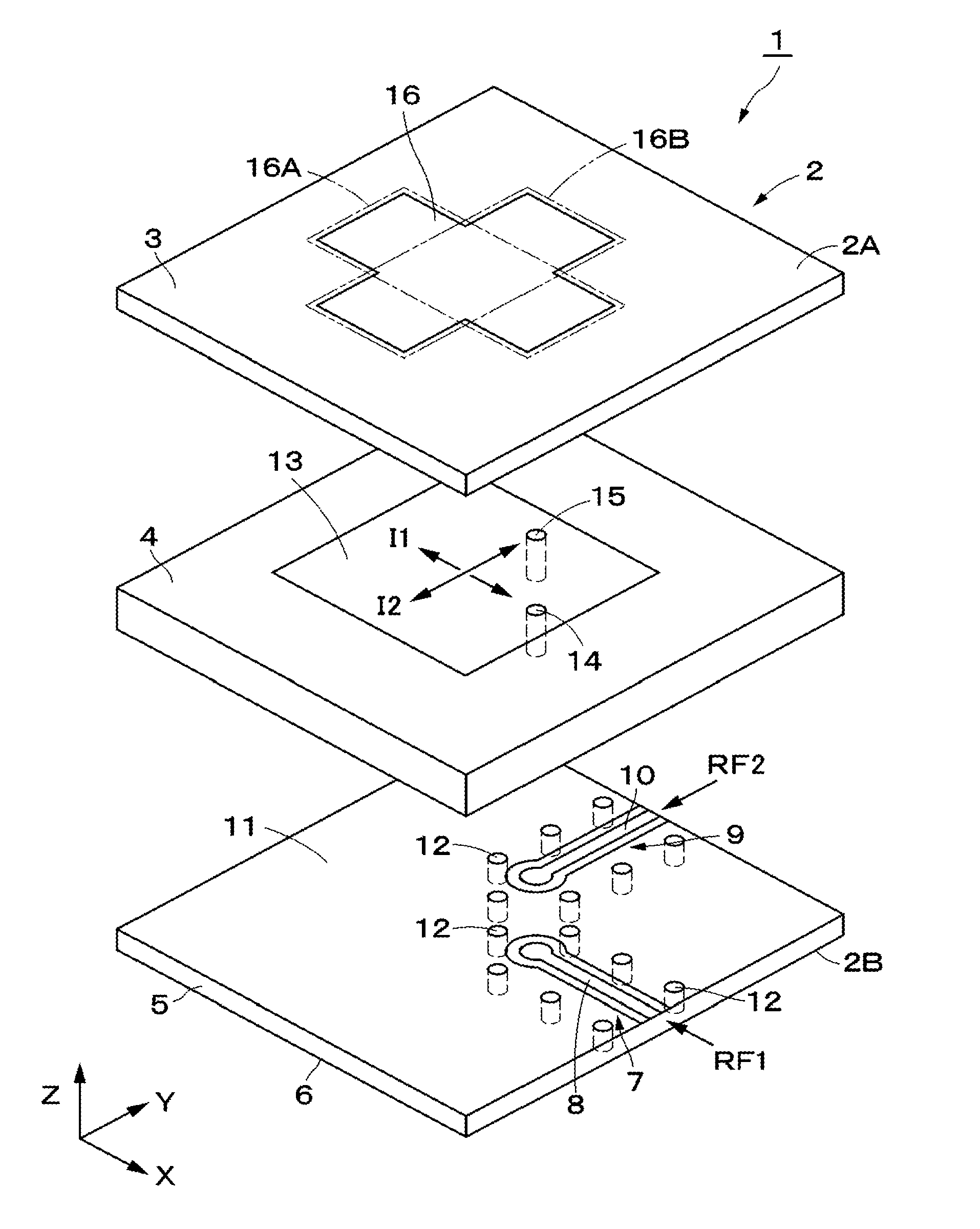
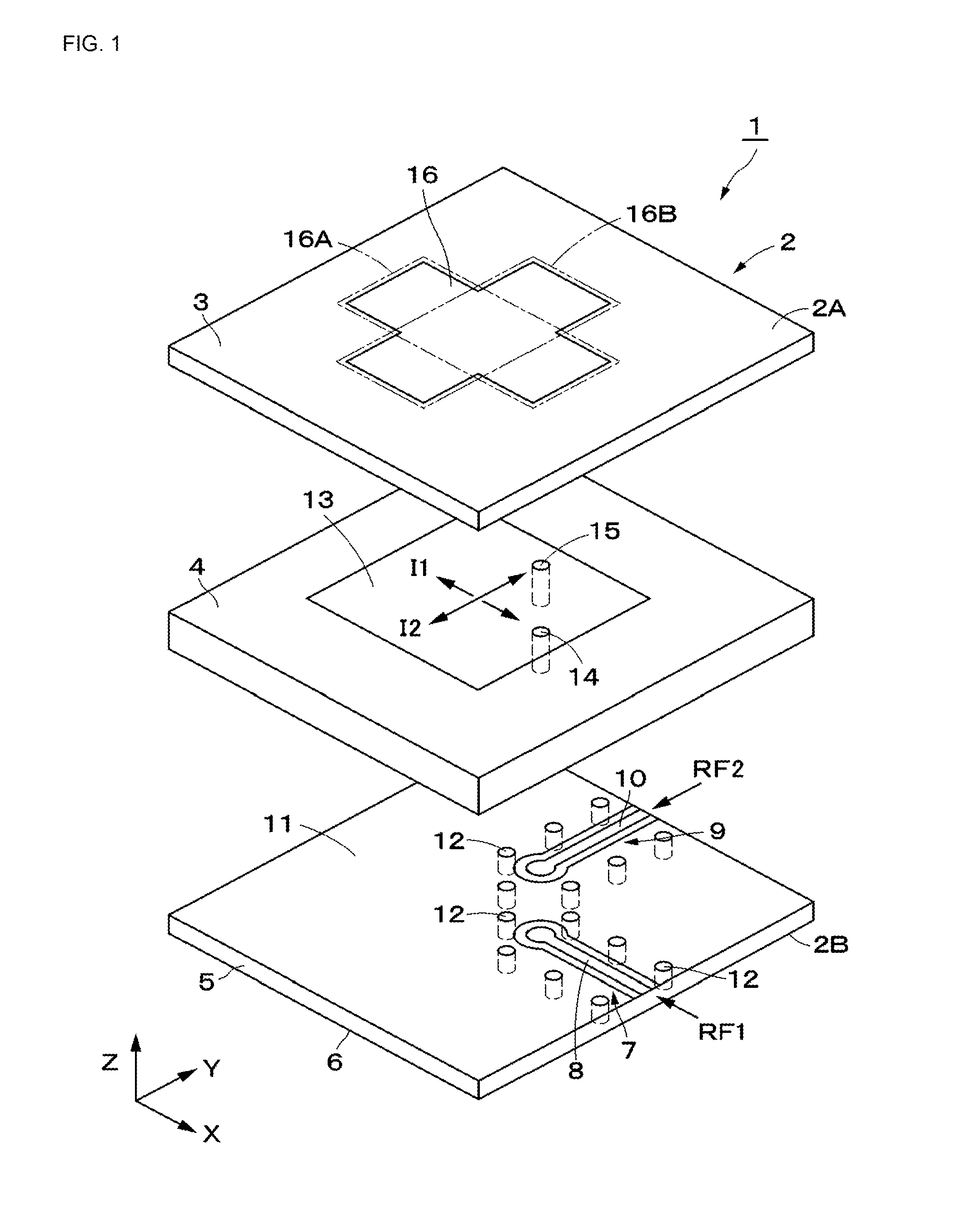
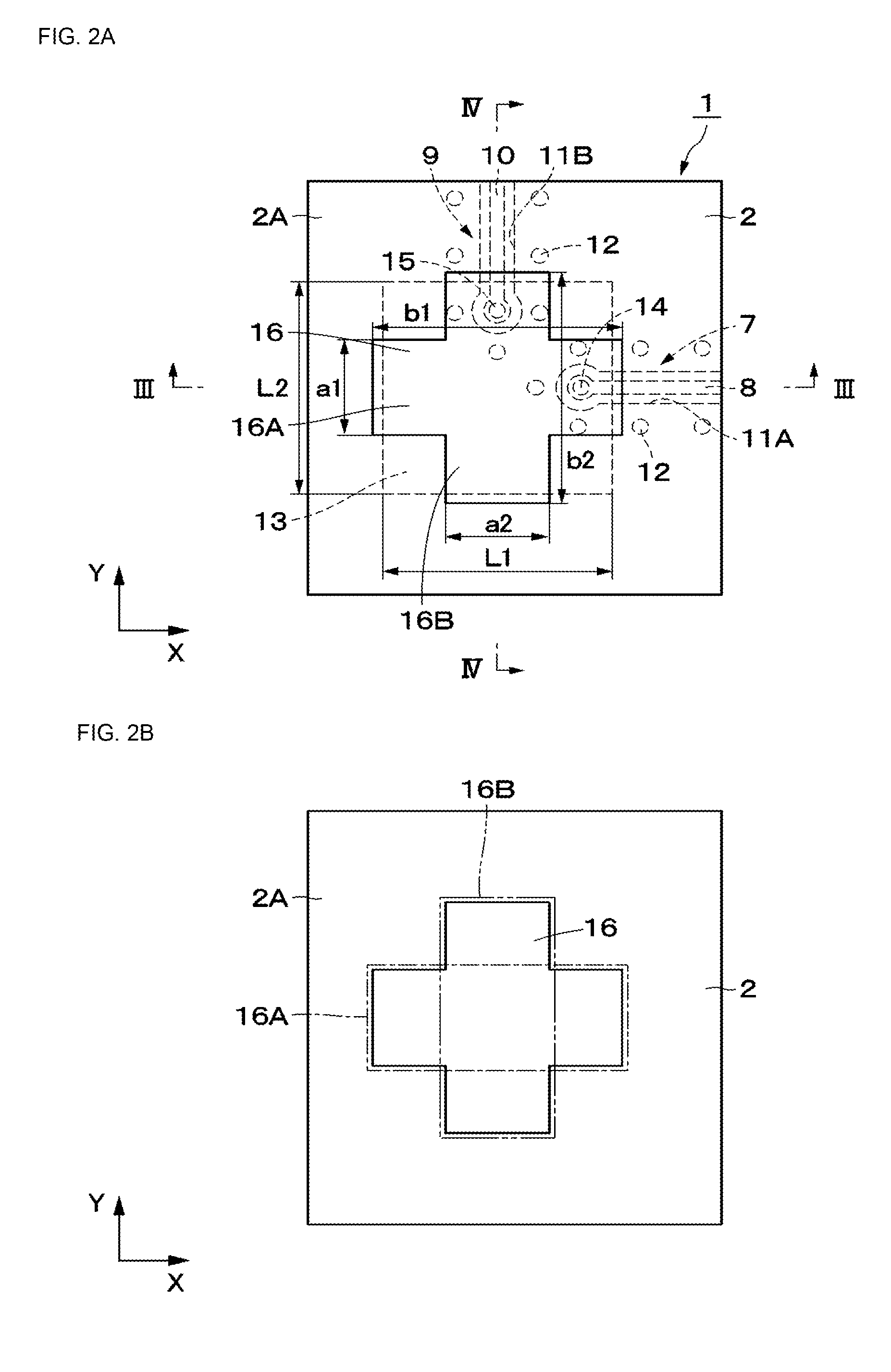
[0037]FIG. 1 to FIG. 4 illustrate a dual-polarized antenna 1 according to a first embodiment. The dual-polarized antenna 1 is configured by a multilayer substrate 2, first and second coplanar lines 7 and 9, an internal ground layer 11, a radiating element 13, a passive element 16, and the like described later.

[0038]The multilayer substrate 2 is formed in a flat plate shape extending in two directions, for example, an X-axis direction and a Y-axis direction in parallel among the X-axis direction, the Y-axis direction, and a Z-axis direction orthogonal to one another. The multilayer substrate 2 has a length dimension of approximately several mm, for example, in the Y-axis direction, has a length dimension of approximately several mm, for example, in the X-axis direc...


PUM


Abstract

In a multilayer substrate (2), an internal ground layer (11) is provided at a position between insulating layers (4) and (5) and a radiating element (13) is provided at a position between insulating layers (3) and (4). A first coplanar line (7) is connected to an intermediate position of the radiating element (13) in an X-axis direction, and a second coplanar line (9) is connected to an intermediate position of the radiating element (13) in a Y-axis direction. A passive element (16) is laminated on the upper surface of the radiating element (13) through the insulating layer (3). The passive element (16) is formed in a cross shape in which a first patch (16A) extending in the X-axis direction and a second patch (16B) extending in the Y-axis direction are orthogonal to each other.

Description

FIELD OF THE INVENTION[0001]The present invention relates to a dual-polarized antenna capable of being shared by two polarized waves, for example.DESCRIPTION OF THE RELATED ART[0002]Patent Document 1 discloses a microstrip antenna (patch antenna). In the microstrip antenna, a radiating element and a ground layer that are opposed to each other with a dielectric thinner than a wave length being interposed therebetween, for example, are provided and a passive element is provided at a radiant surface side of the radiating element. Further, Patent Documents 2 and 3 disclose dual-polarized antennas in which a radiating element is formed in a substantially square shape and feeding points are provided on axes orthogonal to each other. Patent Document 4 discloses a dual-polarized antenna in which power is fed to a patch antenna by a strip line formed in a cross shape. In addition, Patent Document 5 discloses a planar antenna for a single-direction polarized wave, which reduces a high-order m...

Claims


Application Information

Patent Timeline
Patent Type & Authority Applications(United States)
IPC IPC(8): H01Q9/04
CPCH01Q9/045H01Q1/38H01Q5/378
Inventor SUDO, KAORUNAKAJIMA, MASAYUKI
Owner MURATA MFG CO LTD
Why Eureka
Try Eureka