Control circuit and control method for capacitive touch panel

a capacitive touch panel and control circuit technology, applied in the field of capacitive touch panel control circuit and control method, can solve the problems of high base capacitance, low performance, and increase the parasitic capacitance between adjacent sensors, so as to reduce the parasitic capacitance, enhance the sensing effect, and reduce the base capacitance of the touch panel

Inactive Publication Date: 2010-05-06
ELAN MICROELECTRONICS CORPORATION
View PDF11 Cites 83 Cited by
  • Summary
  • Abstract
  • Description
  • Claims
  • Application Information

AI Technical Summary

Benefits of technology

[0010]In the control circuit and control method for a capacitive touch panel according to the present invention and applications thereof, in-phase signals are provided for lowering parasitic capacitances between adjacent conductors and decreasing a bas

Problems solved by technology

When the base capacitance is high, the change of capacitance is less apparent and therefore difficult to detect, which leads to low performance.
The conventional differential detection method, though capable of increa

Method used


Image

  • Control circuit and control method for capacitive touch panel
  • Control circuit and control method for capacitive touch panel
  • Control circuit and control method for capacitive touch panel

Examples


Embodiment Construction

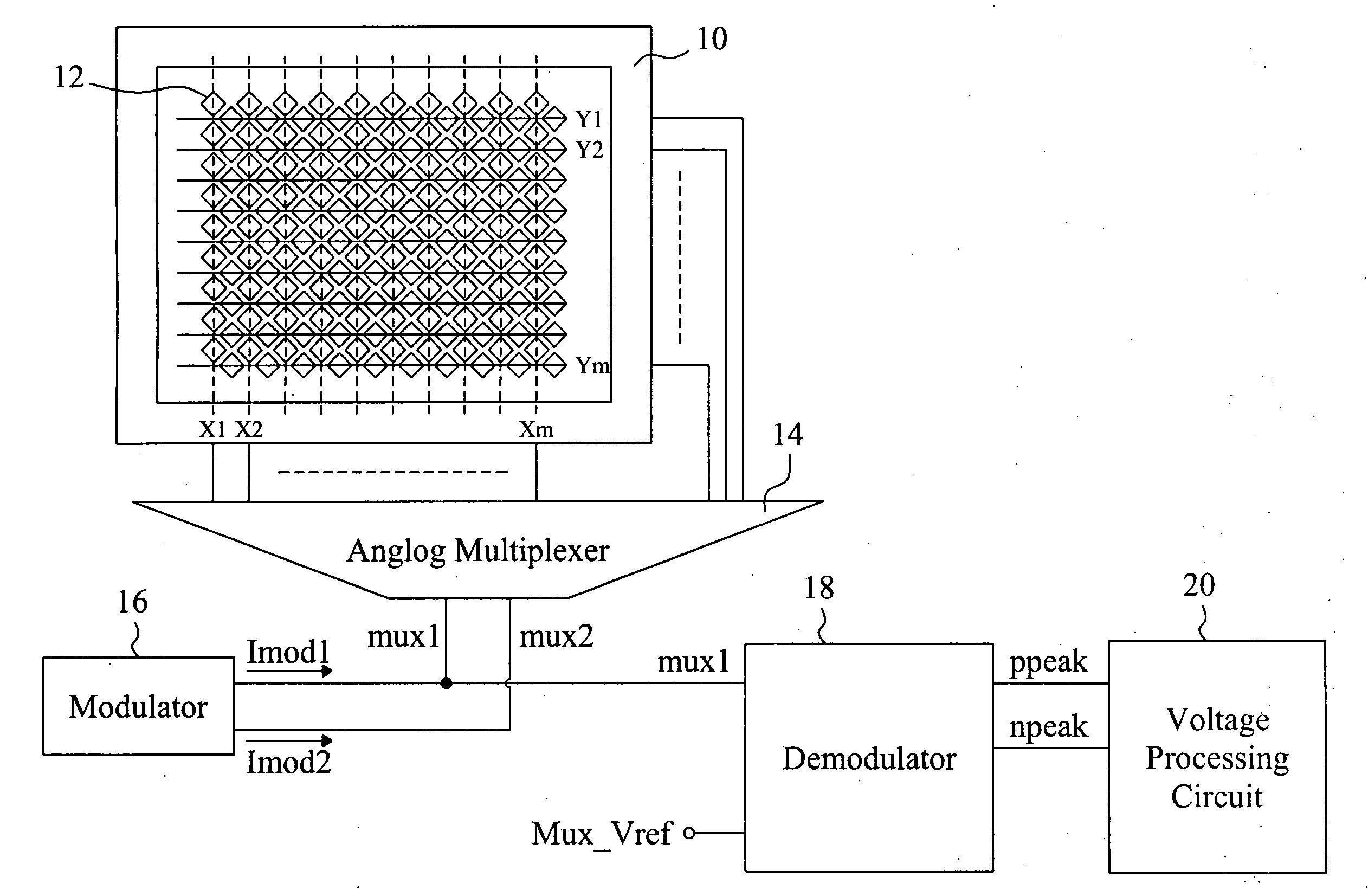
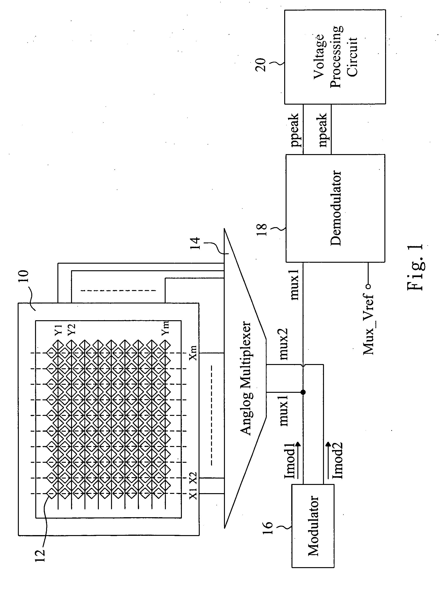
[0030]Referring to FIG. 1 for a schematic drawing of an embodiment of the present invention, a capacitive touch panel 10 is provided with a plurality of sensors 12. The vertically aligned sensors 12 are connected by a conductive wire so as to form traces X1, X2 . . . Xm while the horizontally aligned sensors 12 form traces Y1, Y2 . . . Ym. A modulator 16 produces current signals that are supplied to traces selected by an analog multiplexer 14 and are thus modulated into signals mux1 and mux2. A demodulator 18 demodulates the signal mux1 with a reference signal Mux_Vref so as to produce signals ppeak and npeak that are supplied to a voltage processing circuit 20. The voltage processing circuit 20 transforms a voltage difference between the signals ppeak and npeak so as to obtain information corresponding to changes of capacitance on the capacitive touch panel 10.

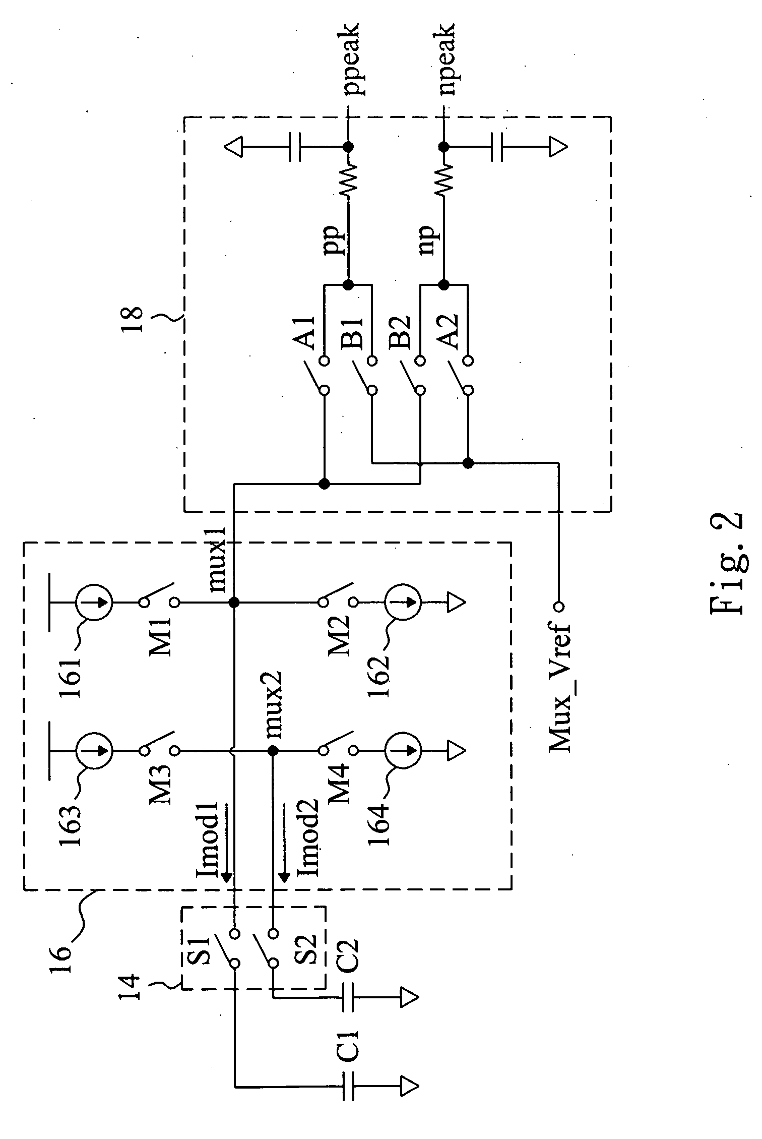
[0031]FIG. 2 is a circuit diagram for the embodiment of FIG. 1 while FIG. 3 is an oscillogram of signals at single ends of ...


PUM


Abstract

A control circuit and a control method for a capacitive touch panel are provided. Therein, while a scanning signal charges and discharges each trace on the capacitive touch panel, a signal in phase with the scanning signal is provided to traces adjacent to the scanned trace or a ground layer under the scanned trace so as to lower parasitic capacitances between the scanned trace and the ground layer or other traces, thereby decreasing a base capacitance of the capacitive touch panel and enhancing a sensing result of the control circuit as well as providing a shielding effect and reducing noise interference so that the capacitive touch panel has improved performance.

Description

BACKGROUND OF THE INVENTION[0001]1. Technical Field[0002]The present invention is related to a capacitive touch panel, more particularity, to a control circuit and control method for a capacitive touch panel.[0003]2. Description of Related Art[0004]Capacitive touch panels are lightweight, compact, power saving, and durable so as to be widely used as panels of notebook computers, cell phones, personal digital assistants, and multimedia players. Typically, a capacitive touch panel comprises a printed circuit board, a piece of glass, or a plastic film as a substrate. A conductive film of metal or indium tin oxide or a pattern made of other materials is printed on the substrate as sensors, whose shapes and sizes vary with intended applications. When the touch panel is touched by a stylus or a user's finger, change in capacitance takes place at the sensors. A control circuit detects the changes of capacitance at the sensors to obtain information input by the user and thus enable touch co...

Claims


Application Information

Patent Timeline
IPC IPC(8): G06F3/045
CPCG06F3/044G06F3/0443G06F3/0445G06F3/0446
Inventor HUANG, CHUN-CHUNGWANG, TSUN-MINLIN, CHUN-YU
Owner ELAN MICROELECTRONICS CORPORATION
Why Eureka
Try Eureka