Infrared reflective member, and infrared reflective device and method of making same

Inactive Publication Date: 2009-01-15
TOYODA GOSEI CO LTD
View PDF5 Cites 31 Cited by
  • Summary
  • Abstract
  • Description
  • Claims
  • Application Information

AI Technical Summary

Benefits of technology

[0022]In yet another aspect the present invention provides a method of making an infrared reflective member comprising the steps of: preparing the filler material as a solvent; adding the colloidal particles as a solute to the solvent to prepare a solution; stirring the solution by ultrasound to prepare a colloidal dispersion; and producing a film from the colloidal dispersion to form the infrared reflective member. Through ultrasound stirring i

Problems solved by technology

However, expensive equipment and complex manufacturing processes can be problems in the manufacture of these films.
However, where use

Method used


Image

  • Infrared reflective member, and infrared reflective device and method of making same
  • Infrared reflective member, and infrared reflective device and method of making same
  • Infrared reflective member, and infrared reflective device and method of making same

Examples


Example

[0031]The preferred embodiments for carrying out the invention will be described below.

(1) General Configuration of Infrared Reflective Device 10

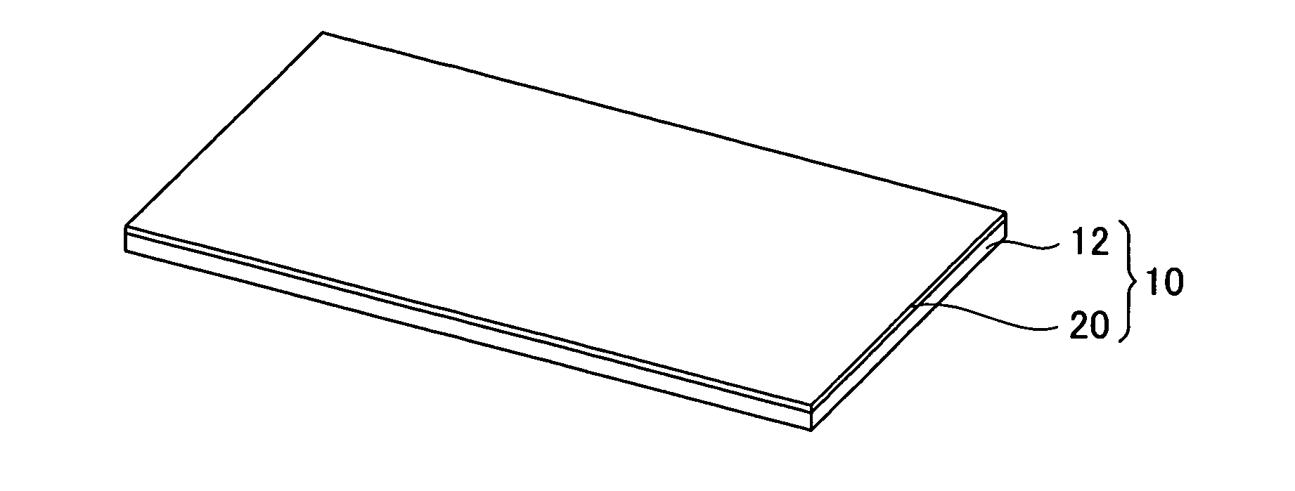
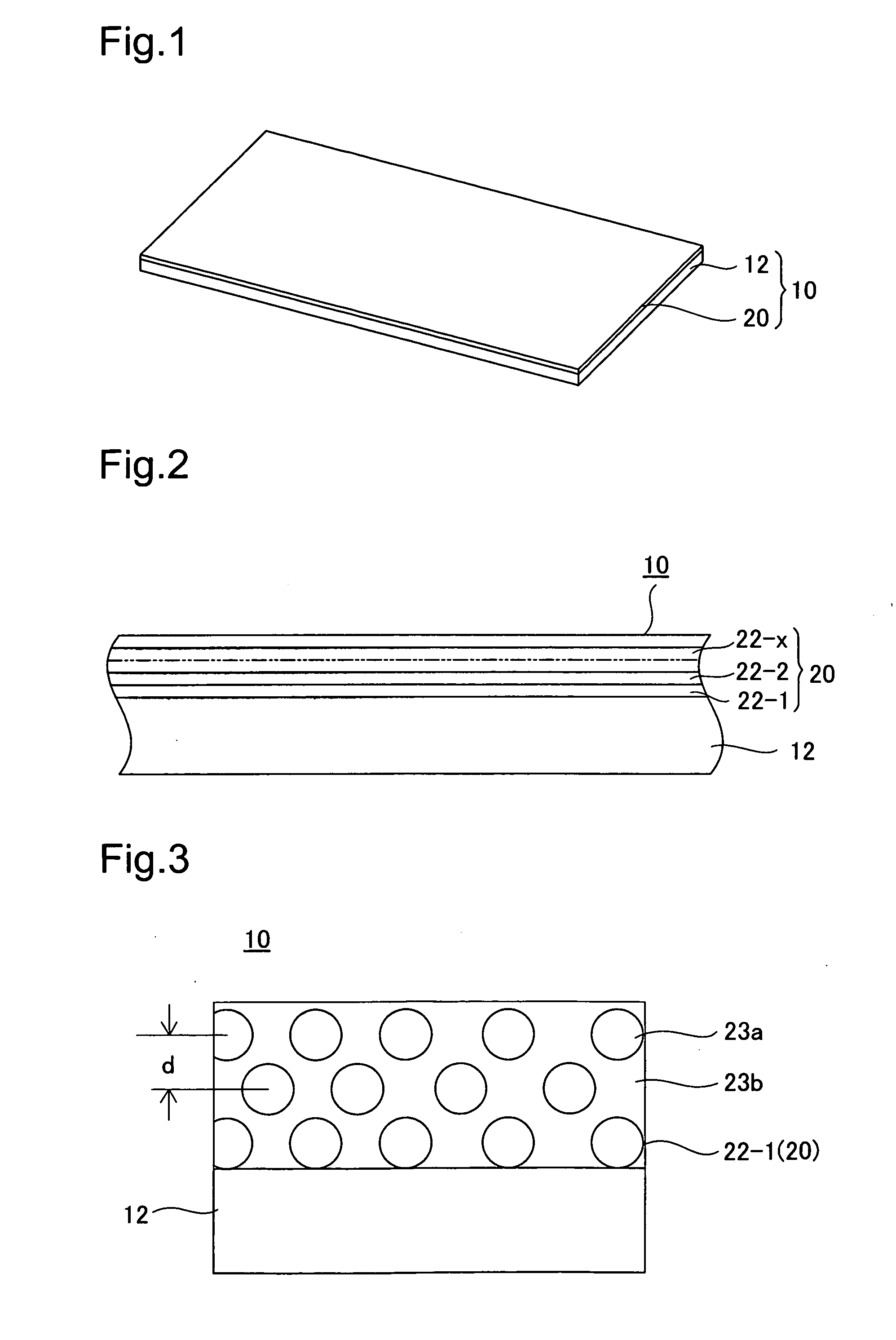
[0032]FIG. 1 is a perspective view depicting an infrared reflective device 10 pertaining to an embodiment of the present invention; and FIG. 2 is an enlarged fragmentary sectional view of FIG. 1. In FIGS. 1 and 2, the infrared reflective device 10 includes a transparent support 12 and an infrared reflective laminate 20 applied over the transparent support 12. The transparent support 12 is a panel capable of transmitting visible light and formed of sheet glass, a transparent resin, or the like. The infrared reflective laminate 20 is composed of a plurality of infrared reflective members 22-1, 22-2, . . . , 20-2x, . . . , 22-n stacked in n layers. Each individual infrared reflective member 20-2x has a thickness of between 1 and 1000 μm.

[0033]FIG. 3 is an illustration depicting in model form an infrared reflective device 10 having only a singl...


PUM

PropertyMeasurementUnit
Transmittivityaaaaaaaaaa
Particle sizeaaaaaaaaaa

Abstract

The infrared reflective device includes infrared reflective members which reflect infrared rays. The infrared reflective members include colloidal particles arranged at regular spacing, and a filler material intervening in the spaces between the colloidal particles. The difference between the refractive index of the colloidal particles and the refractive index of the filler material is set so as to be 0.05 or less in the visible light region and 0.1 or above in the infrared region, whereby visible light is transmitted while infrared rays are reflected.

Description

[0001]This application claims the benefit of and priority from Japanese Application No. 2007-184596 filed Jul. 13, 2007, the content of which is incorporated herein by reference.BACKGROUND OF THE INVENTION[0002]1. Field of the Invention[0003]The present invention relates to an infrared reflective member which transmits visible light while reflecting infrared rays, to an infrared reflective device utilizing the material, and method of making the same.[0004]2. Description of the Related Art[0005]Practicable technologies proposed for reflecting infrared wavelengths contained in sunlight while transmitting the visible light wavelengths include a transparent conductive film of material such as tin oxide (JP 06-048776 A), or a laminate of an oxide or similar material (JP 2005-089244A). However, expensive equipment and complex manufacturing processes can be problems in the manufacture of these films. Another known technology proposes a reflective panel composed of an infrared reflective fi...

Claims


Application Information

Patent Timeline
IPC IPC(8): F21V9/04B05D5/06
CPCG02B5/208G02B5/206
Inventor ANDO, HIROAKIMIYAZAKI, TAKESHINAKAMURA, HIROSHIISHII, MASAHIKO
Owner TOYODA GOSEI CO LTD
Why Eureka
Try Eureka