Structure And Method For Attaching Shield Case To Circuit Board, Electronic Component Module And Portable Telephone

a technology of electronic components and shield cases, applied in the direction of printed circuits, electrical devices, printed circuit aspects, etc., can solve the problems of short circuits and the like, the communication function of information terminals is affected, and the fabrication time and cost is increased

Inactive Publication Date: 2009-01-15
FUJIFILM CORP
View PDF12 Cites 36 Cited by
  • Summary
  • Abstract
  • Description
  • Claims
  • Application Information

AI Technical Summary

Benefits of technology

[0028]With the above-described structures of the present invention, the present invention is capable of preventing solder balls and solder flux from entering inside a shield case. Furthermore, ...

Problems solved by technology

Electromagnetic waves are emitted from these electronic components, and the electromagnetic waves may cause impairment of communications functions of the information terminal.
However, when a soldering operation is being performed, solder balls, solder flux and the like may be scattered, and may ingress through the gaps M into the shield case 104.
If the solder balls/solder flux adher...

Method used


Image

  • Structure And Method For Attaching Shield Case To Circuit Board, Electronic Component Module And Portable Telephone
  • Structure And Method For Attaching Shield Case To Circuit Board, Electronic Component Module And Portable Telephone
  • Structure And Method For Attaching Shield Case To Circuit Board, Electronic Component Module And Portable Telephone

Examples


Embodiment Construction

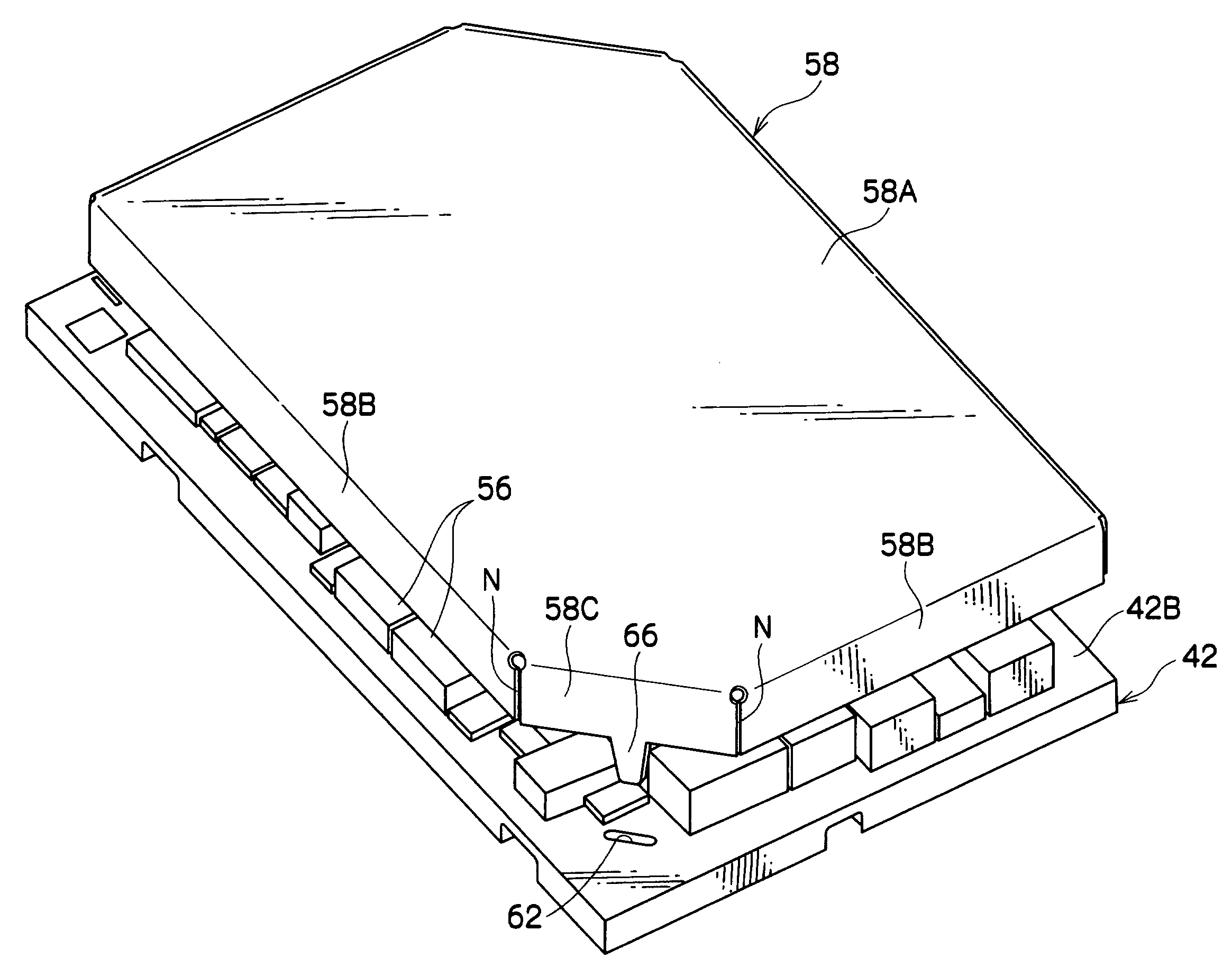
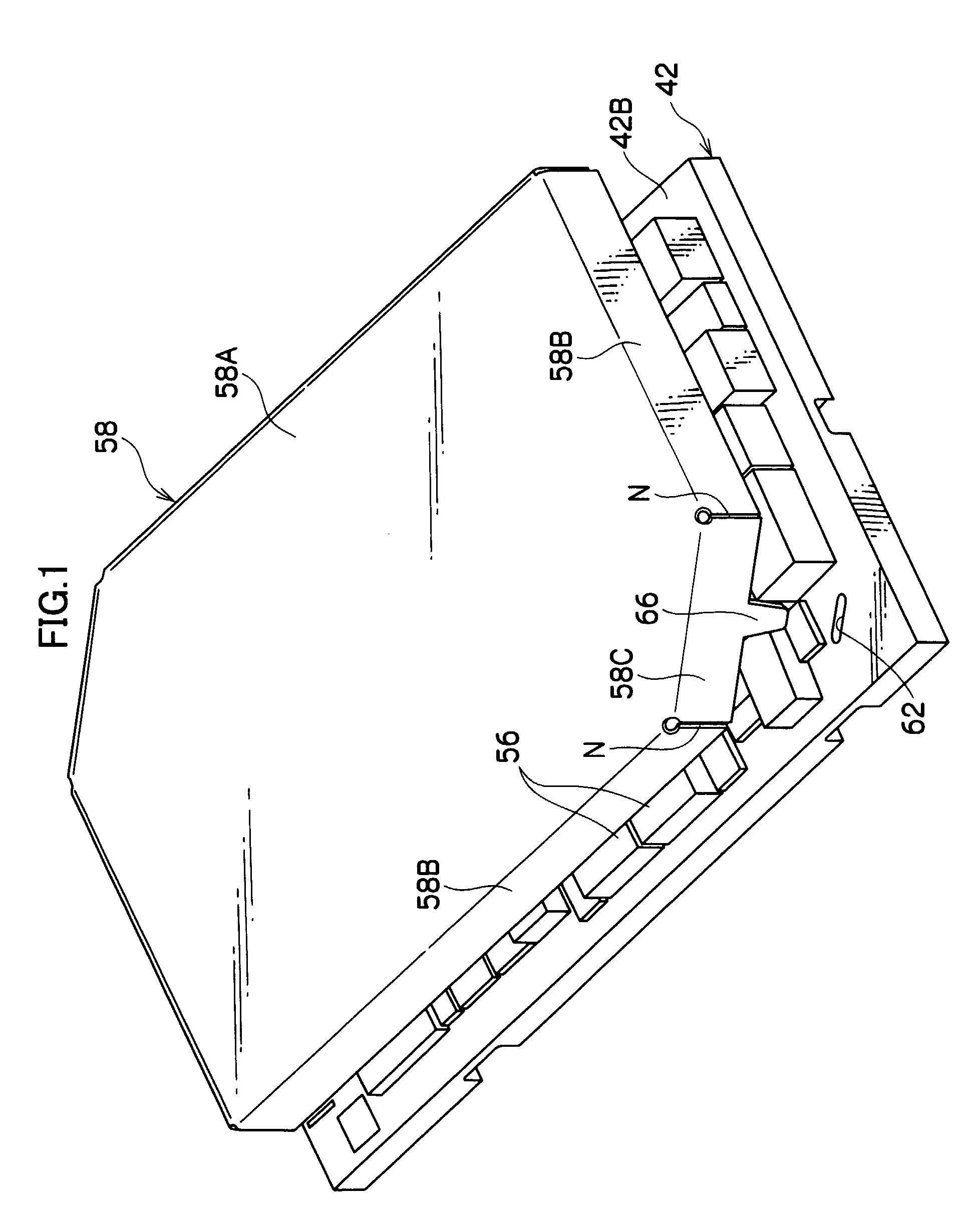
[0041]FIG. 1 shows a structure for attaching a shield case to a circuit board of an embodiment of the present invention.

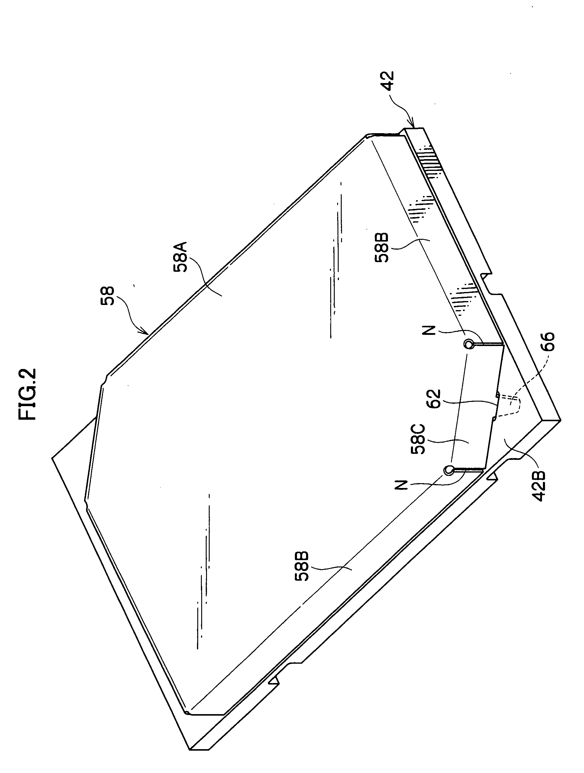
[0042]Electronic components 56 such as resistors, capacitors, semiconductor chips and the like are mounted at a front face 42B of a circuit board 42. In order to protect these electronic components 56, a box-like shield case 58 is attached to the front face 42B of the circuit board 42. A case made of metal is employed as the shield case 58. Because the shield case 58 is attached to the circuit board 42, electromagnetic waves which are emitted from the electronic components 56 on the circuit board 42 will be blocked by the shield case 58 and will not affect, for example, communications functions of a portable telephone 10 (see FIGS. 4A and 4B).

[0043]The shield case 58 is formed in a box shape with a substantially rectangular shape in plan view, with opposing corner portions thereof cut away to form short side faces 58C. A toe portion 66 is projected from a substanti...


PUM


Abstract

A structure for attachment of a shield case to a circuit board. Electronic components are mounted at one face of the circuit board. The shield case is for covering the electronic components and blocking electromagnetic waves. The attachment structure includes toe portions, formed to protrude from the shield case, and holes formed in the circuit board, at which the toe portions can be inserted. The toe portions are fixed to the circuit board by being inserted into the holes and soldered to soldering lands at the other face of the circuit board. Thus, it is possible to prevent solder balls and solder flux entering the shield case, it is further possible to reserve space for soldering lands, with sizes that are required for fixing of the shield case, at a rear face of the circuit board, and it is possible to attach the shield case to the circuit board strongly.

Description

CROSS-REFERENCE TO RELATED APPLICATION[0001]This application claims priority under 35 USC 119 from Japanese Patent Application No. 2005-006367, the disclosure of which is incorporated by reference herein.TECHNICAL FIELD[0002]The present invention relates to a structure and process for attaching a shield case to a circuit board, and to a portable telephone at which an imaging module which is structured using this shield case attachment structure is installed.BACKGROUND TECHNOLOGY[0003]At an imaging module, an imaging element, a lens and components such as an IC, which is a driver for driving the imaging element, and the like are integrated as a package. The imaging module is installed at an information terminal, such as a portable telephone or the like. Electronic components, such as a CCD and the like, are mounted at a circuit board which structures this imaging module. Electromagnetic waves are emitted from these electronic components, and the electromagnetic waves may cause impair...

Claims


Application Information

Patent Timeline
IPC IPC(8): H05K9/00H05K3/34
CPCH05K3/3405H05K3/3447Y10T29/49142H05K2201/10371H05K2201/10916H05K9/0028
Inventor IMAMURA, TAKASHI
Owner FUJIFILM CORP
Why Eureka
Try Eureka