
Scanning detection device of an x-ray ct apparatus, an x-ray ct system and method of operation of the same

a detection device and a technology of x-ray ct, which are applied in the field of x-ray ct apparatus and x-ray ct (computed tomography) apparatus operation methods, can solve the problems of reducing the radiation intensity of the scanned subject, affecting the patient's treatment, so as to reduce the radiation suffered by the scanned subject, facilitate the user's operation, and reduce the error

Active Publication Date: 2009-01-15
GE MEDICAL SYST GLOBAL TECH CO LLC
View PDF13 Cites 17 Cited by
  • Summary
  • Abstract
  • Description
  • Claims
  • Application Information

AI Technical Summary

Benefits of technology

[0012]Described herein are a method for operating an X-ray CT apparatus and the apparatus itself for solving the above-mentioned problem. More specifically, the embodiments herein provide a method and an apparatus for effectively combining the tube current value parameter, the noise index parameter and the scout scan image, which has good judgment, high image quality, and low radiation amount.
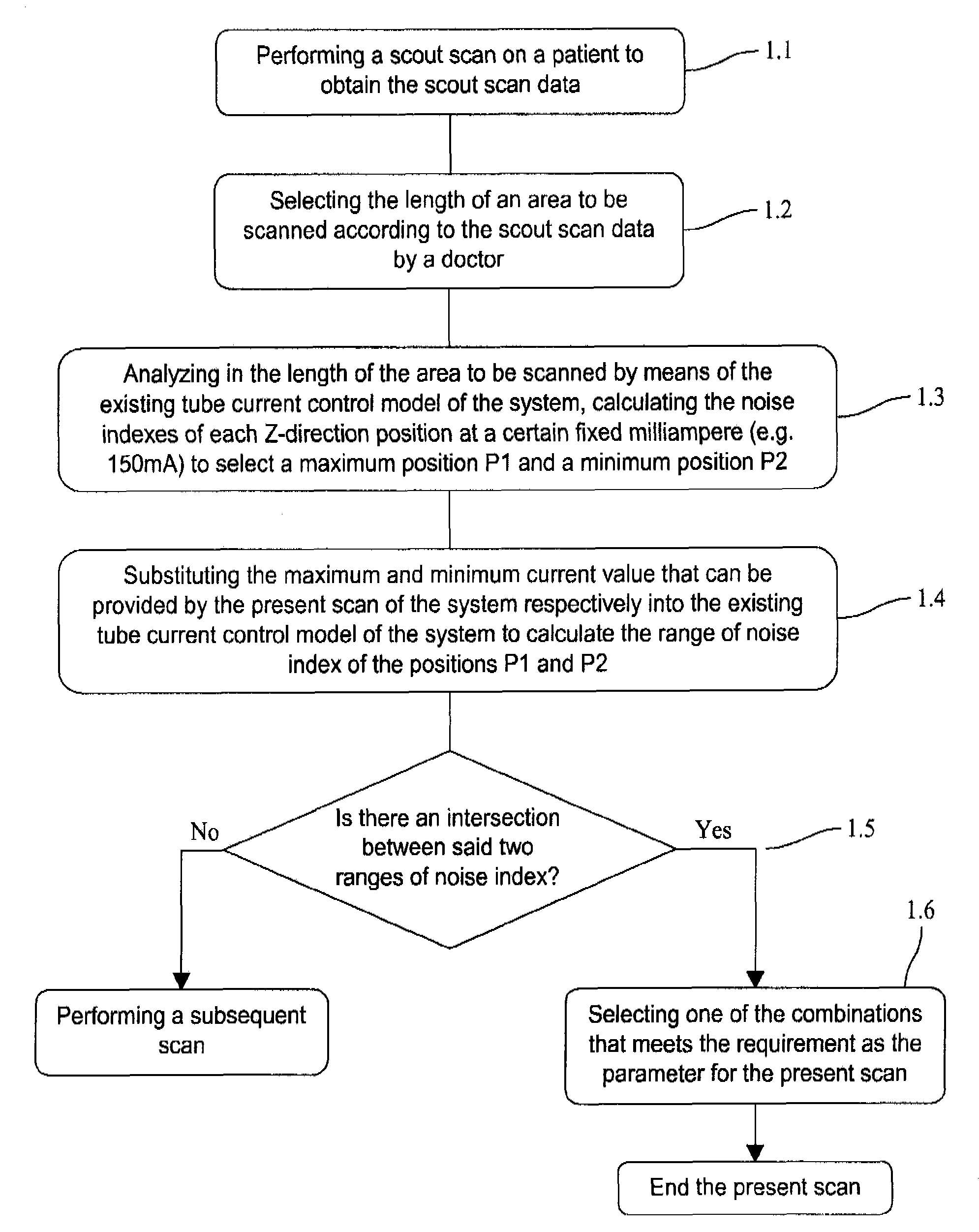
[0039]In another aspect, the embodiments described herein describe performing analysis processing during the scout scan of the subject so as to obtain the range of noise index of the position with the minimum noise index and the range of noise index of the position with the maximum noise index in the length of the area to be scanned, and determine whether there is an intersection between the two ranges of noise index so as to determine whether the system meets the requirement for scanning the subject to be scanned. The method, scanning detection device, and system of the present invention can effectively determine whether the system is in a condition that meets the requirements both for the range of tube current value and for the noise index with respect to the scanned subject, thus preventing the doctor from scanning the patient blindly by using the CT system without considering whether the system meets the requirement for scanning the patient owing to a lack of the method and device for detection and determination in the existing scanning system and preventing the patient from suffering unnecessary radiation. In addition, the present invention establishes a correspondence relationship between the range of current value and the noise index, thus enabling the doctor to select more accurately the condition required by the scanning so as to effectively reduce the radiation suffered by the scanned subject. Furthermore, the present invention establishes a relationship between the tube current control interface and the combination of the range of tube current value and the noise index that meets the requirement, thus enabling the values of the selected combination to be automatically filled into the corresponding box for the range of tube current value and prohibiting the user to enter and modify the range of current value, which facilitates the user's operation and reduces the mistakes that might be caused by the user's operation. The user can also adjust the noise coefficient within the range of noise adjustment so as to obtain better images.

Problems solved by technology

X-ray is known to be harmful to the tissues and organs of human body, so the manufacturers of X-ray CT apparatuses try their best to make the X-ray CT apparatuses they manufactured obtain better scan images with the lowest X-ray radiation amount as it can be.
First, if the doctor is not clear about the setting of the noise index of the operated CT apparatus, then when the doctor sets a noise index to scan the patient, the noise index of the resulted scan image is quite different from the value set by the user. This makes the doctor doubt the result of examination and even re-scan the patient, thus making the patient suffer from more X-ray radiation.
Second, when testing the function of the apparatus, failure of test sometimes occurs. After resetting the range of tube current and noise index in the corresponding positions as shown in FIG. 3, the previously failed testing item may pass smoothly. But sometimes, even if the range of tube current value and / or index are reset, the test still fails, thus the tester may become confused and wonder what on earth the appropriate range of test value should be.
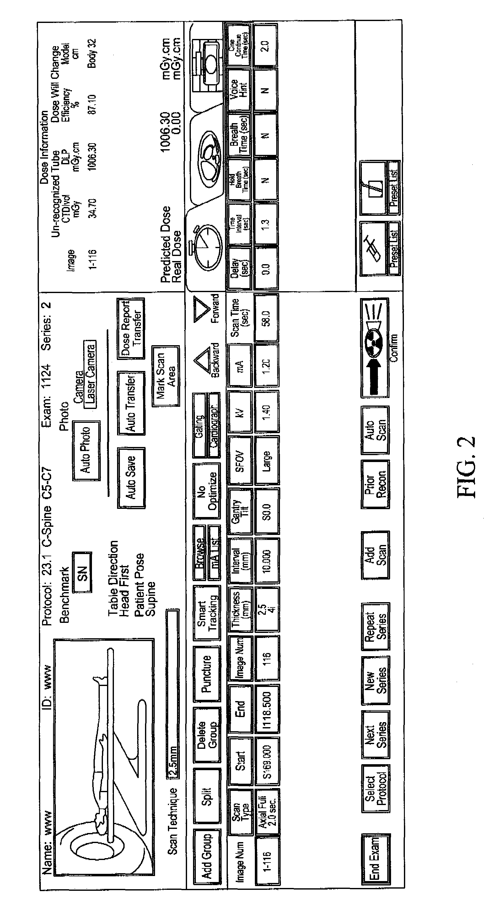
Third, the noise index and the range of tube current value are independent from each other in the tube current control parameter input user operation interface of the existing CT system, as shown in FIG. 5. Therefore, in this tube current control interface, the input of the range of tube current value does not influence the input of the noise index, and vice versa.
Such serious mismatch makes the scan image in a mess and with a lot of noise, as a result, it might be necessary to re-scan the patient, thereby making the patient suffer from more X-ray radiation.
The noise index of such output image is not consistent with the actual noise index, which also makes the patient suffer from unnecessary radiation dosage.
Thus during operation, when the user inputs one parameter, the system cannot automatically display the range of the other parameter matching said input parameter.
And the user has to set the other parameter according to his experience, and this may result in a great difference between the output scan image and the set parameters.
Accordingly, the condition of the patient cannot be truly reflected or the patient is made to accept too much radiation.
In addition, such X-ray CT apparatus having the tube current value and the noise index set independently makes the doctor blindly scans an object to be scanned without knowing whether said system has the scanning condition for the object to be scanned in which the requirements for the tube current value and the noise index are both met.

Method used


Image

  • Scanning detection device of an x-ray ct apparatus, an x-ray ct system and method of  operation of the same
  • Scanning detection device of an x-ray ct apparatus, an x-ray ct system and method of  operation of the same
  • Scanning detection device of an x-ray ct apparatus, an x-ray ct system and method of  operation of the same

Examples


Embodiment Construction

[0052]Embodiments of the invention are described in detail below with reference to the accompanying figures, but the invention is not limited to such embodiments.

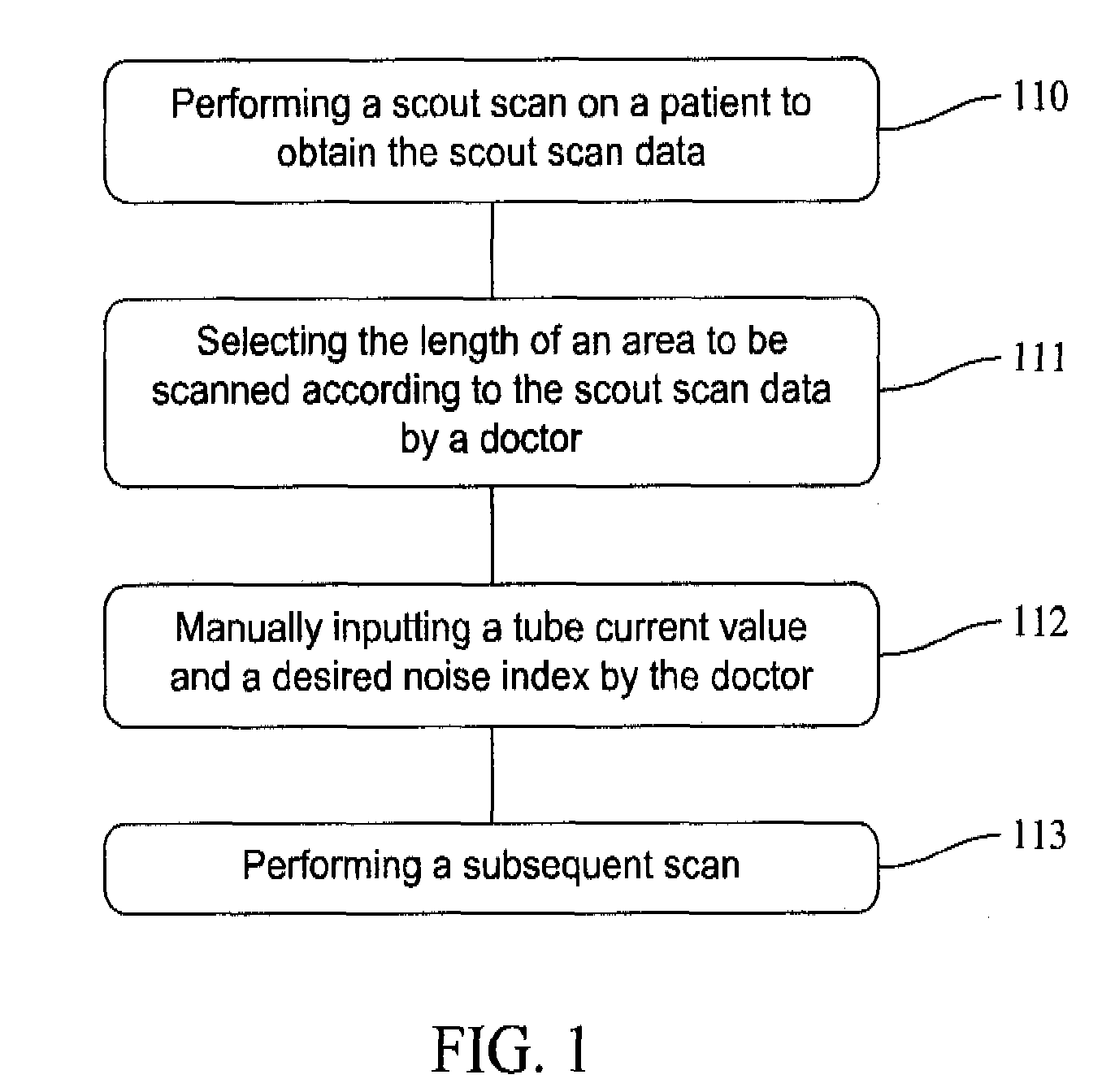
[0053]When the X-ray CT apparatus scans a subject, it performs a scout scan first to obtain the length of the area to be scanned, then conducts analysis according to the tube current control model and sets input values of current and noise index to perform a subsequent scan. The present invention makes some improvement to the existing X-ray CT apparatus and the scanning method thereof.

[0054]FIG. 7 is a block diagram of an X-ray CT system with a tube current control model according to the present invention. Said system is an embodiment of the present invention. An embodiment of the device of the present invention is illustrated by the structure of said system.

[0055]The X-ray CT system with a tube current control model according to the present invention comprises a scanning gantry 1 for performing a radiation scan including s...


PUM


Abstract

Method of operating an X-ray CT apparatus and the corresponding apparatus and system thereof. A method includes analyzing scout scan data to obtain a position with a minimum noise index and a position with a maximum noise index, calculating noise indexes at the two positions in a range of a maximum and a minimum tube current that can be provided by the system by means of a tube current control model so as to obtain two ranges of noise index, and determining whether there is an intersection between the two ranges of noise index. If such an intersection exists, a combination of the range of tube current value and the range of noise index that meets the requirement is selected within the intersection to control the system to proceed with a subsequent scan. If no such intersection exists, the system ends the present scan.

Description

CROSS REFERENCE TO RELATED APPLICATIONS[0001]This application claims the benefit of Chinese Patent Application No. 200710126224.7 filed Jun. 22, 2007, which is hereby incorporated by reference in its entirety.BACKGROUND OF THE INVENTION[0002]The subject matter disclosed herein relates to an operation method of an X-ray CT apparatus and an X-ray CT (Computed Tomography) apparatus, in particular to a method for detecting whether an X-ray CT apparatus can meet the requirement for scanning an object to be scanned and the CT apparatus and system using said detection method.[0003]X-ray is known to be harmful to the tissues and organs of human body, so the manufacturers of X-ray CT apparatuses try their best to make the X-ray CT apparatuses they manufactured obtain better scan images with the lowest X-ray radiation amount as it can be. Thus an intelligent tube current control model has been invented and applied to X-ray CT apparatuses, which can ensure a uniform noise value among the scan ...

Claims


Application Information

Patent Timeline
IPC IPC(8): A61B6/00
CPCA61B6/032A61B6/465A61B6/544A61B6/542A61B6/488
Inventor WANG, XUELI
Owner GE MEDICAL SYST GLOBAL TECH CO LLC
Learn More