
System and method for two-dimensional visualization of temporal phenomena and three dimensional vessel reconstruction

a two-dimensional visualization and temporal phenomenon technology, applied in image enhancement, instruments, angiography, etc., can solve the problems of not receiving much interest in two-dimensional applications involving dsa sequences, limiting 2d visualization applications, and no application has ever been applied to directly facilitate in-room clinical procedures for the whole vessel tr

Active Publication Date: 2009-01-15
SIEMENS HEALTHCARE GMBH
View PDF1 Cites 119 Cited by
  • Summary
  • Abstract
  • Description
  • Claims
  • Application Information

AI Technical Summary

Benefits of technology

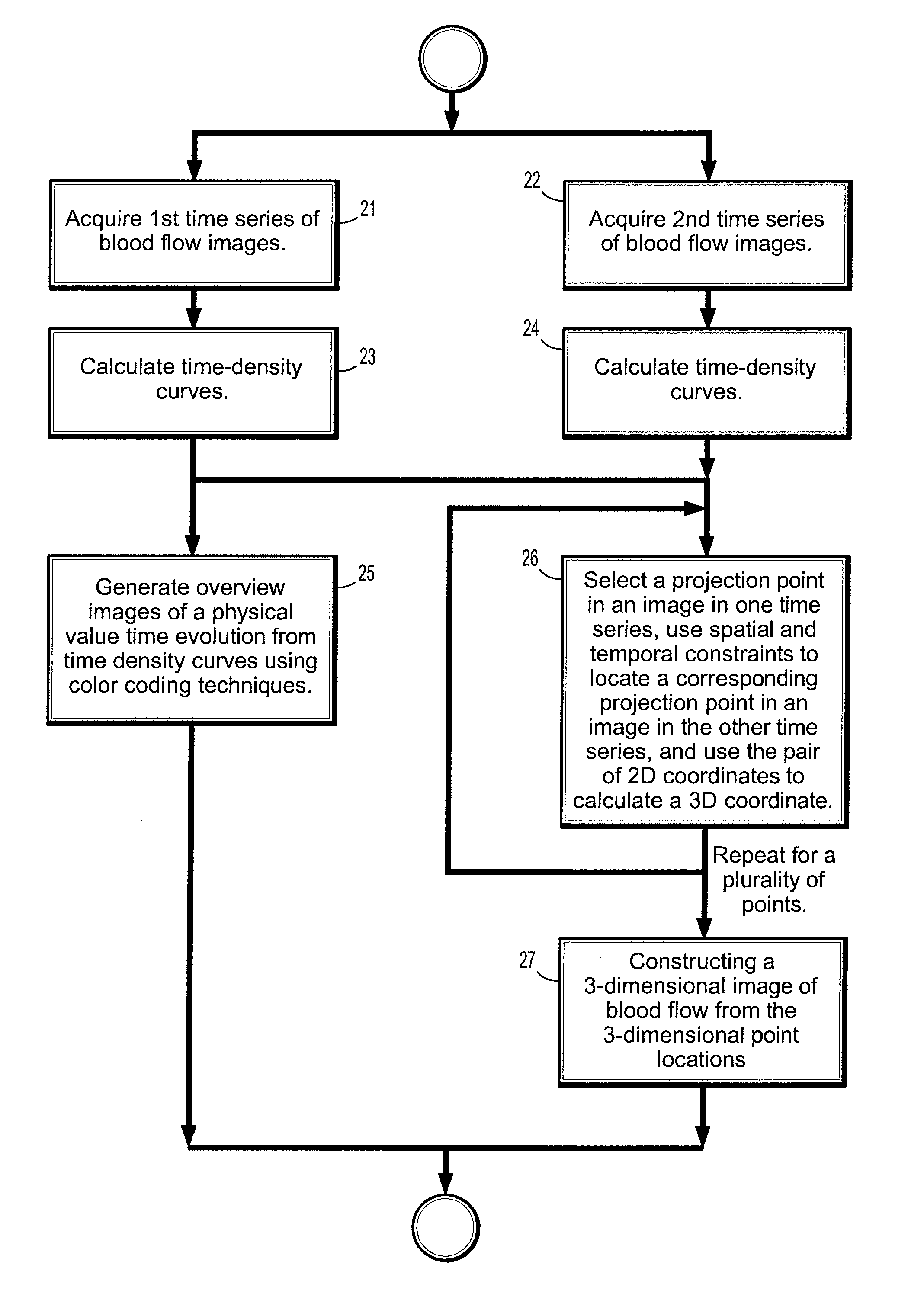
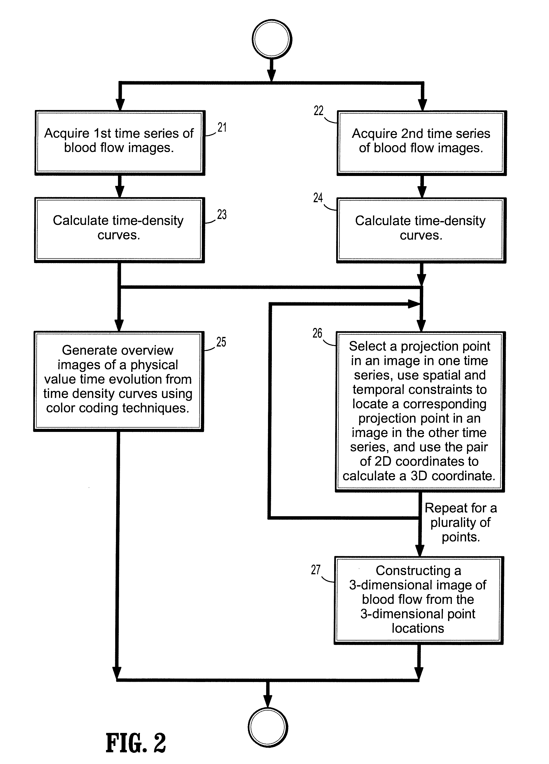
[0005]Exemplary embodiments of the invention as described herein generally include methods and systems for fusing dynamic information with static 3D angiography images for 3D reconstruction using as few as two views taken in a bi-plane imaging geometry to simultaneously provide morphological and functional information. In additional to geometric (epiploar) constraints for the reconstruction of a 3D structure, such as a vessel tree, additional constraints include the use of a time varying physical process, such as contrast flow within vessels and temporal constraints, such as those...

Problems solved by technology

Among all the proposed techniques, none has ever been applied to directly facilitate in-room clinical procedures for the whole vessel tree beyond some limited clinical trials, due to the large computational cost or inaccuracy of the reconstruction.
Interestingly, while color coding of tissue areas based on time-density curves is common in perfusion computed tomography (CT), two-dimensional applications involving DSA sequences have not yet received much interest.
One related work involves segmentation of vessel structures, but is limited to 2D visualization applications.

Method used


Image

  • System and method for two-dimensional visualization of temporal phenomena and three dimensional vessel reconstruction
  • System and method for two-dimensional visualization of temporal phenomena and three dimensional vessel reconstruction
  • System and method for two-dimensional visualization of temporal phenomena and three dimensional vessel reconstruction

Examples


Embodiment Construction

[0028]Exemplary embodiments of the invention as described herein generally include systems and methods for computing a 3D representation of a sparse vascular object from a limited number of views. Accordingly, while the invention is susceptible to various modifications and alternative forms, specific embodiments thereof are shown by way of example in the drawings and will herein be described in detail. It should be understood, however, that there is no intent to limit the invention to the particular forms disclosed, but on the contrary, the invention is to cover all modifications, equivalents, and alternatives falling within the spirit and scope of the invention.

[0029]As used herein, the term “image” refers to multi-dimensional data composed of discrete image elements (e.g., pixels for 2-D images and voxels for 3-D images). The image may be, for example, a medical image of a subject collected by computer tomography, magnetic resonance imaging, ultrasound, or any other medical imagin...


PUM


Abstract

A method for visualizing temporal phenomena and constructing 3D views from a series of medical images includes providing a first time series of digital images of contrast-enhanced blood flow in a patient, each acquired from a same viewing point with a known epipolar geometry, each said image comprising a plurality of intensities associated with an N-dimensional grid of points, calculating one or more time-density curves from said first time series of digital images, each curve indicative of how the intensity at corresponding points in successive images changes over time, and generating one or more overview images from said time density curves using a color coding technique, wherein said each overview image depict how a physical property value changes from said blood flow at selected corresponding points in said first time series of images.

Description

CROSS REFERENCE TO RELATED UNITED STATES APPLICATIONS [0001]This application claims priority from “Two-Dimensional Visualization of Temporal Phenomena and Three Dimensional Vessel Reconstruction from Few Views using Spatial and Temporal Constraints”, U.S. Provisional Application No. 60 / 948,536 of Yatziv, et al, filed Jul. 9, 2007, the contents of which are herein incorporated by reference in their entirety.TECHNICAL FIELD [0002]This disclosure is directed to computing a 3D representation of a sparse (vascular) object from a limited number of views.DISCUSSION OF THE RELATED ART [0003]Blood flow rate and velocity information inside vasculature is important for the monitoring of endovascular treatments of arteriovenous malformations, diagnosis of vascular disease, and radio therapy treatment. Thus, the task of performing accurate and reliable assessment of instantaneous blood flow has been extensively researched. Out of many approaches, digital subtraction angiography has been found to...

Claims


Application Information

Patent Timeline
IPC IPC(8): G06K9/00
CPCA61B6/469A61B6/481A61B6/504G06T7/0065G06T2207/30104G06T2207/10016G06T2207/10116G06T2207/30016G06T7/20G06T7/55
Inventor STROBEL, NORBERTYATZIV, LIRON
Owner SIEMENS HEALTHCARE GMBH
Learn More