Compressor
a compressor and compression tube technology, applied in the field of compressors, can solve the problems of increasing the cost of setting the tank and the piping, the large labor and considerable time required for laying out the devices, etc., and achieves the effect of reducing the resultant load, easy and safe transportation, and short period of tim
- Summary
- Abstract
- Description
- Claims
- Application Information
AI Technical Summary
Benefits of technology
Problems solved by technology
Method used
Image
Examples
first embodiment
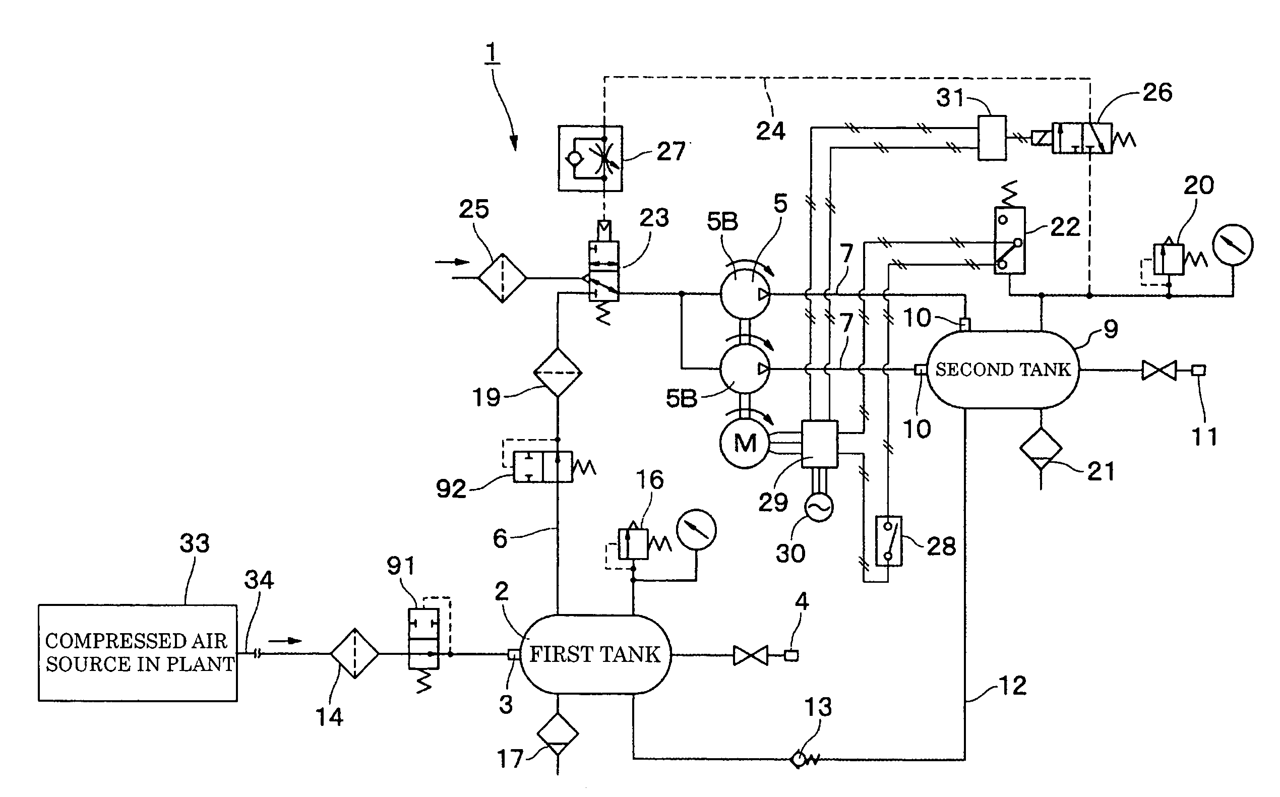
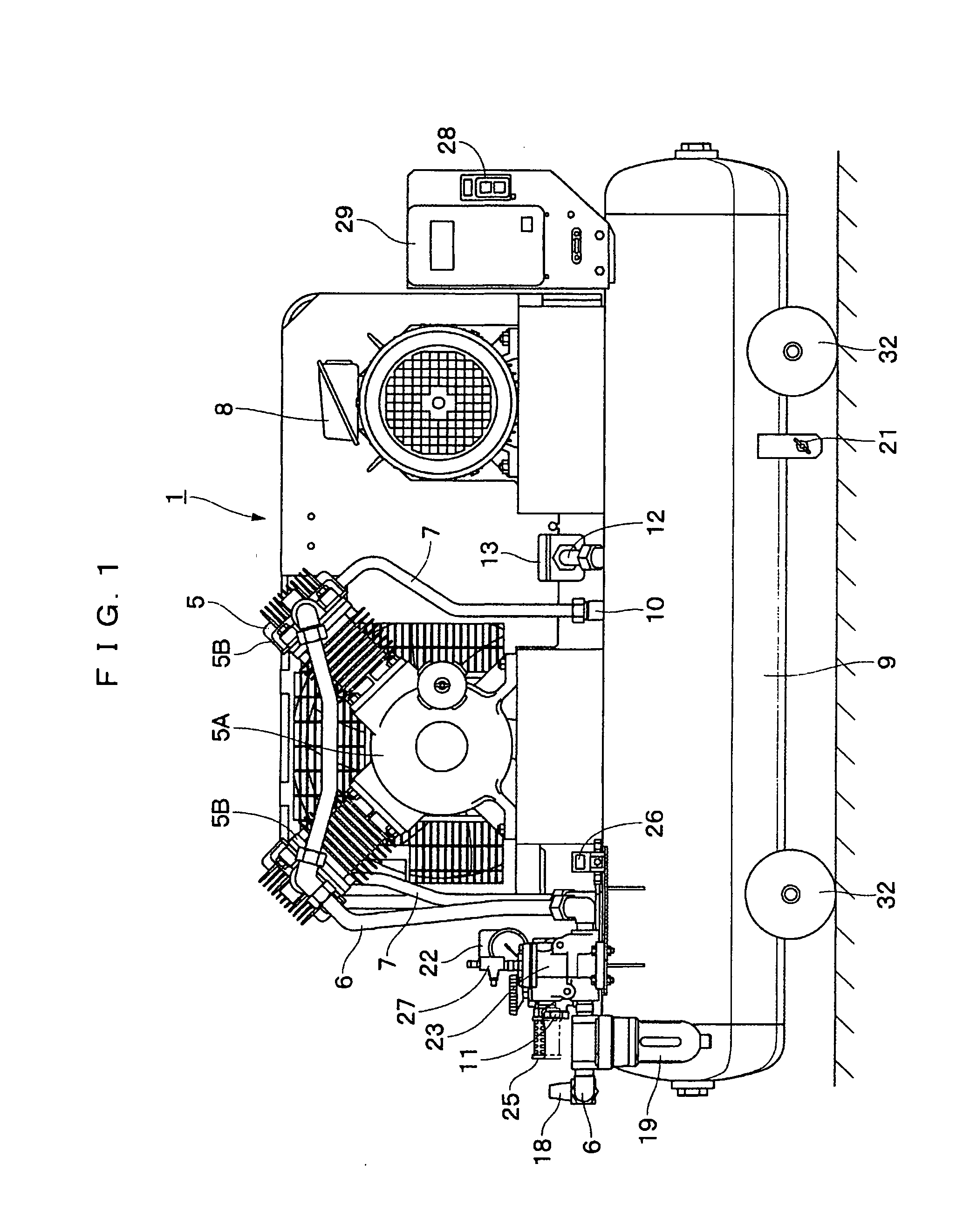
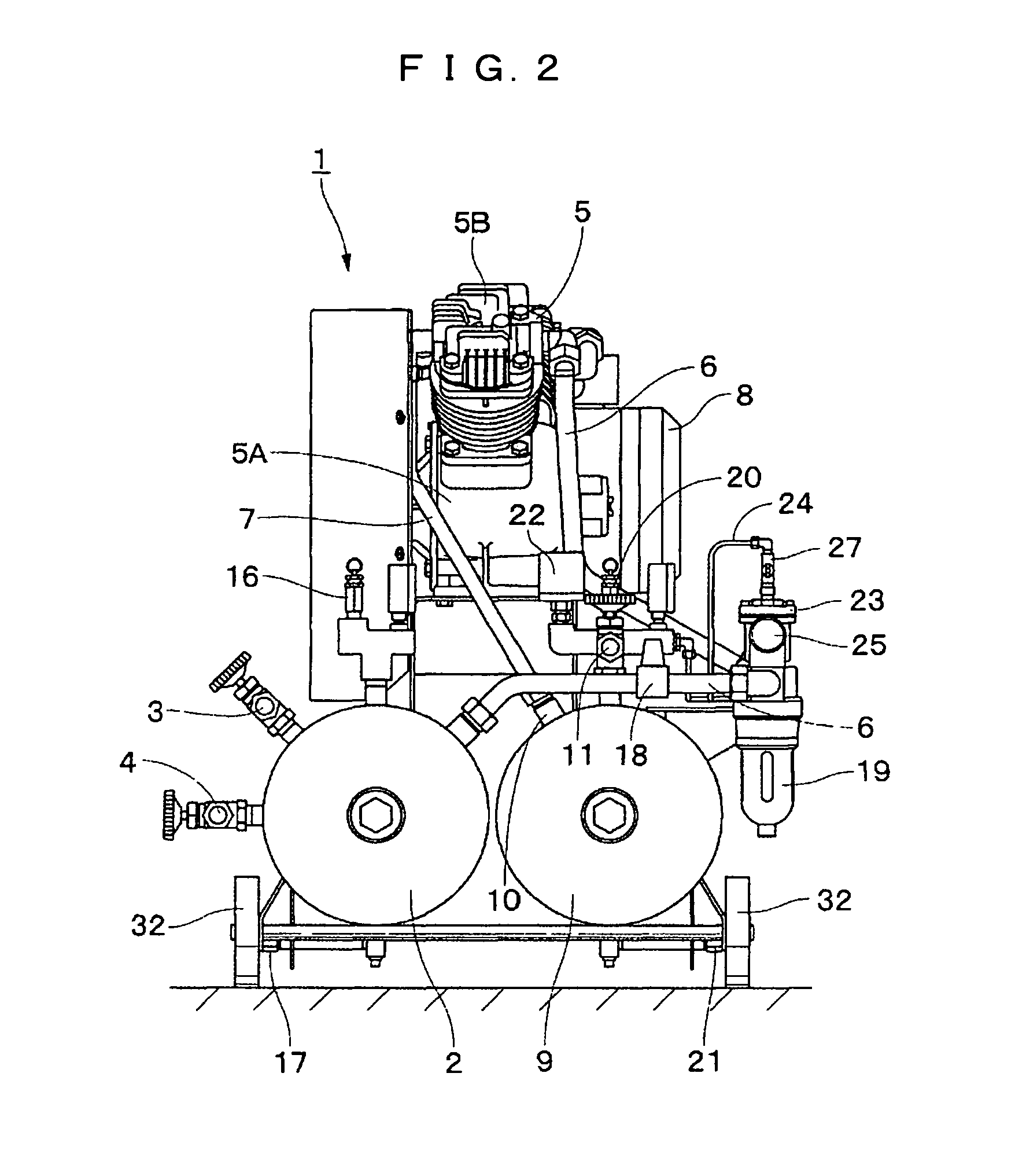
[0059]Configurations of the first and the second tanks 2 and 9 will be described hereinafter. In the first embodiment, the first tank 2 has substantially the same outer configuration as that of the second tank 9 in consideration with the productivity and the balance in the external appearance. Each of the first and the second tanks 2 and 9 may be formed to have the minimum possible volume for the purpose of making the air compressor 1 light-in-weight and compact.
[0060]A communication pipe 12 communicates the first tank 2 with the second tank 9, and distributes the low compressed air which has been supplied to the first tank 2 to the second tank 9. A check valve 13 to be described later is provided in an intermediate position of the communication pipe 12.
[0061]The check valve 13 is provided in the intermediate position of the communication pipe 12 for communicating the first tank 2 with the second tank 9. The check valve 13 allows the low compressed air to flow from the first tank 2 ...
second embodiment
[0103]the booster type air compressor according to the present invention will be described referring to FIG. 5.
[0104]In the embodiment, the first tank and the second tank have the cylindrical bodies in parallel with each other in the longitudinal direction, and vertically installed on the mount surface. In the second embodiment, the same components as those in the first embodiment will be designated with the same reference codes with dash.
[0105]FIG. 5 shows a booster type air compressor 41 according to the second embodiment. A first tank 42 and a second tank 43 which form the air compressor 41 have the cylindrical bodies in parallel with each other in the longitudinal direction, and vertically installed on the mount surface using leg portions 42A and 43A. This makes it possible to reduce the space requiring installation of the air compressor 41.
[0106]A main body 5′ of the compressor and an electric motor 8′ are mounted on a base 44 above the first tank 42 and the second tank 43. A p...
third embodiment
[0110]A booster type air compressor according to the present invention will be described referring to FIGS. 6 and 7.
[0111]In the embodiment, the first tank and the second tank are arranged having a gap therebetween, and the main body of the compressor is installed between the first and the second tanks so as to be partially fit therebetween.
[0112]In the embodiment, the single assembly formed by combining the first tank, the main body and the second tank includes handgrips at both ends of the cylindrical body in the longitudinal direction such that the assembly is gripped. The third embodiment has substantially the same structure as that of the first embodiment. The main feature of the embodiment will only be described, and description and drawing of the other portion will be omitted.
[0113]FIG. 6 shows a booster type air compressor 51 according to a third embodiment. FIG. 7 shows a first tank 52 as a cylindrical body, and a second tank 53 arranged in parallel with and apart from the ...
PUM
| Property | Measurement | Unit |
|---|---|---|
| pressure | aaaaa | aaaaa |
| pressure | aaaaa | aaaaa |
| pressure | aaaaa | aaaaa |
Abstract
Description
Claims
Application Information
 - R&D
- Intellectual Property
- Life Sciences
- Materials
- Tech Scout
- Unparalleled Data Quality
- Higher Quality Content
- 60% Fewer Hallucinations
Browse by: Latest US Patents, China's latest patents, Technical Efficacy Thesaurus, Application Domain, Technology Topic, Popular Technical Reports.
© 2025 PatSnap. All rights reserved.Legal|Privacy policy|Modern Slavery Act Transparency Statement|Sitemap|About US| Contact US: help@patsnap.com


