
Application of RFID labels

a technology of rfid labels and labels, applied in the field of application of rfid labels, can solve the problems of making the application step more difficult, and achieve the effect of easy application of the required parts to the package and minimal technical effor

Inactive Publication Date: 2009-01-15
MANROLANAD AG
View PDF3 Cites 6 Cited by
  • Summary
  • Abstract
  • Description
  • Claims
  • Application Information

AI Technical Summary

Benefits of technology

[0008]The object of the present invention is to provide a process for applying the required parts to a package easily and with minimal technical effort.

Problems solved by technology

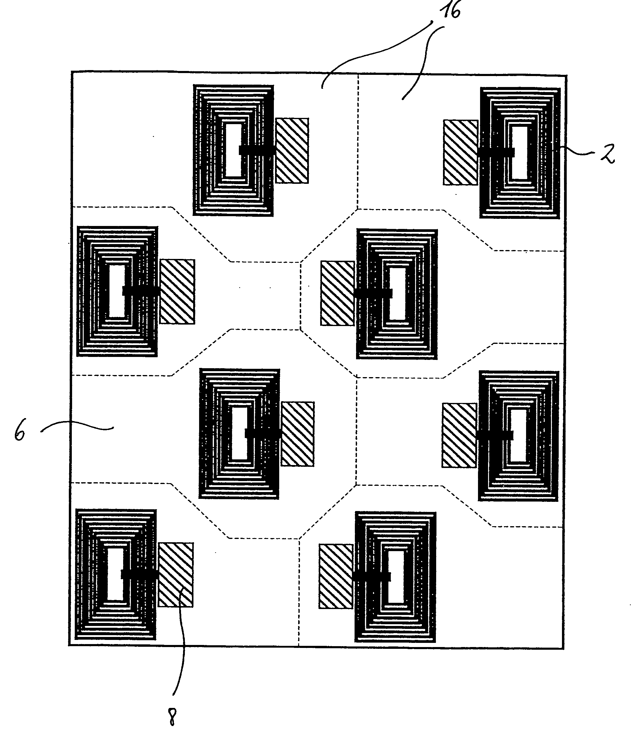
This application step is made more difficult by the fact that the copies are arranged on the sheet in such a way as to conserve space and are thus arranged in various columns and rows.

Method used


Image

  • Application of RFID labels
  • Application of RFID labels
  • Application of RFID labels

Examples


Embodiment Construction

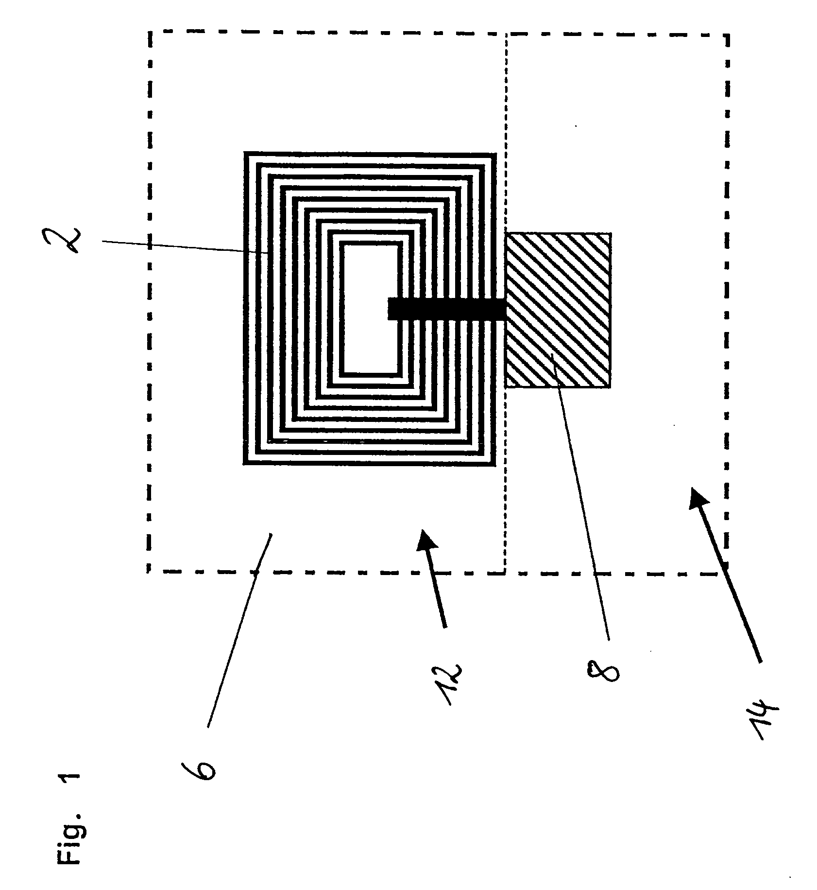
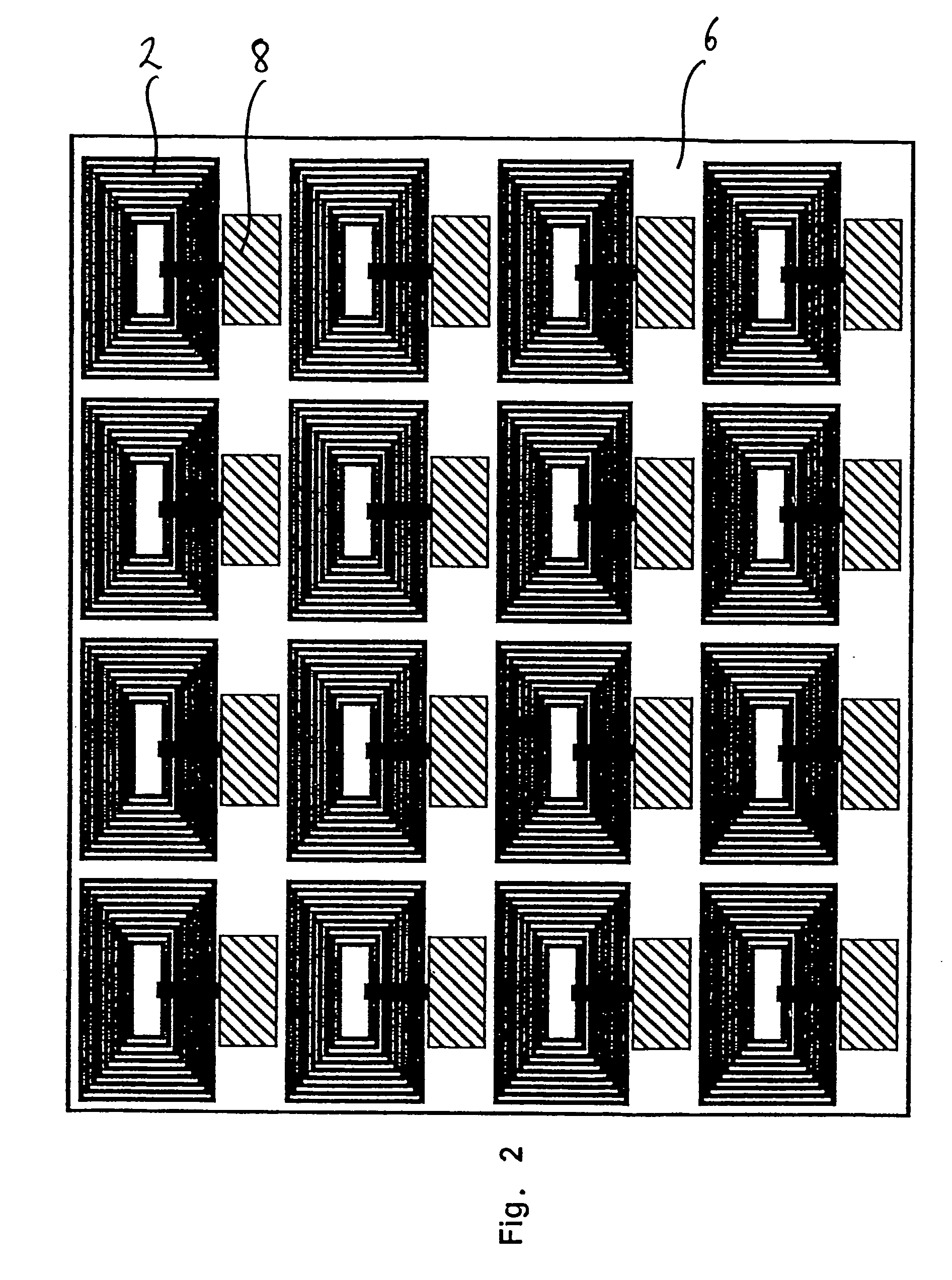
[0015]As can be seen from FIG. 1, the antenna 2 and, not shown, a part of the oscillating circuit which are required for the proper functioning of an RFID label can be applied to a section 12 of the substrate 6 which is suitable for application by use of printing technology. According to the invention, this can be done by offset printing, or directly or indirectly by means of a letterpress plate. After printing, the only further step required is to attach the IC chip 8, which usually does not have a housing, by means of a bonding or soldering process to a section 14 of the substrate 6 which is suitable for mechanical application. It is advantageous to print a multitude of antennas 2 onto one substrate 6 (FIG. 2).

[0016]With respect to the design of the antenna, the following parameters are of interest: the inductance, the coil area, the ohmic (active) resistance, and the mutual capacitance between the windings. Deviations from the characteristic values can make it impossible for cont...


PUM

PropertyMeasurementUnit
conductiveaaaaaaaaaa
lengthaaaaaaaaaa
poweraaaaaaaaaa

Abstract

Disclosed is a method for producing an RFID label with the aid of a printing process. The aim of the invention is make it easy to apply the parts required onto the label while completing the label in a simple manner. Said aim is achieved by applying at least one portion of the antenna and the resonant circuit required for the function to the printing material by means of sheet-fed offset printing or directly or indirectly with the aid of a relief printing plate. The resonant circuits or chips are applied individually or to a packaging that is to be created or filled in the same alignment once several copies of the labels have been produced on one sheet and have been separated therefrom.

Description

CROSS-REFERENCE TO RELATED APPLICATIONS[0001]This is a U.S. national stage of application No. PCT / EP2005 / 001051, filed on 3 Feb. 2005. Priority is claimed on the following application(s): Country: Germany, Application No.: 10 2004 007 457.7, Filed: 13 Feb. 2004; the content of which is incorporated here by reference.BACKGROUND OF THE INVENTION[0002]The invention pertains to a process for producing RFID labels.[0003]The invention describes various processes for producing RFID (Radio Frequency Identification) labels, also called “smart labels”. The basis of intelligent labels (RFIDs, smart labels) is so-called transponder technology. Its great advantage lies in the wireless link between the label and the reader. This can greatly accelerate the mechanical process of data acquisition, because the reader no longer needs to be linked optically with the label. Thus, for example, the content of a box or of a whole pallet can be acquired without error. Security codes can also be stored in th...

Claims


Application Information

Patent Timeline
Patent Type & Authority Applications(United States)
IPC IPC(8): H01L21/50H01P11/00B41F17/00B41M1/22B41M3/00G06K19/077H05K3/12H10K99/00
CPCB41F17/00B41M1/22G06K19/07749H01L51/0004Y10T29/49018H05K3/1275H05K2203/0534H05K2203/1545H05K2203/161H05K3/12H10K71/13
Inventor WALTHER, THOMASBAUMANN, REINHARDWEISS, ROBERTDILLING, PEER
Owner MANROLANAD AG
Learn More