
Control for the display device for a communication terminal

Inactive Publication Date: 2009-01-15
SIEMENS AG
View PDF5 Cites 16 Cited by
  • Summary
  • Abstract
  • Description
  • Claims
  • Application Information

AI Technical Summary

Benefits of technology

[0008]An object of the invention is thus to make the operation of appliances with display devices more economic and more convenient.
[0013]The use of the method makes it possible to operate a display device only when it is actually required, thus saving resources. This advantageously relates on the one hand to energy saving and on the other hand to lengthening the life, which is particularly important when the display device comprises components (for example organic light-emitting diodes) which are subject to increased wear.
[0014]A communication terminal according to the invention accordingly has a reduced power consumption as well as an increased life (MTBF=Mean Time Between Failure). If the communication terminal according to the invention is operated by means of batteries or rechargeable batteries, the embodiment according to the invention ensures a longer life before the battery needs to be replaced, or before the rechargeable batteries need to be recharged.
[0015]In the case of the communication arrangement according to the invention, the reduced power consumption, the longer life of the display device and the capability to prevent unauthorized, improper use of the communication terminal as such, or of individual functions of the communication terminal, in a simple and user-friendly manner (preferably without contact and without any additional manual operating step) should be stressed as being particularly advantageous.
[0017]If the identity of the user is recorded and his authorization is checked for control of the activation and / or deactivation, on the one hand it is possible to reduce the use of the appliance by unauthorized users, while on the other hand the appliance can also advantageously be operated in those environments in which a plurality of potential users are located in the near field of the appliance. In this case, the display device is activated only when at least one of the recorded potential users is actually authorized to use that appliance.
[0020]It is particularly advantageous for the display device to use organic light-emitting diodes, so-called OLEDs. Display devices with OLEDs are mechanically flexible, are physically small and are easily legible. The disadvantages of OLED technology, that is to say the greater power consumption than LED display devices and the shorter life are overcome by the use of methods according to the invention to such an extent that the OLEDs can be used in a worthwhile manner even in appliances which are operated all the time, such as communication terminals.

Problems solved by technology

The display devices of conventional communication terminals are generally in the form of liquid crystal displays (LCD) which on the one hand have an extremely long life and on the other hand consume very little power.
Liquid crystal displays are subject to the disadvantage that they are passive, that is to say they are not self-illuminating and therefore must be combined with an external light source at least in poor lighting conditions (at dusk and when it is dark).
At least in the case of appliances operated by batteries or rechargeable batteries, the power consumption of these light sources has a considerable influence on the usage time of the appliance, so that, for example, in mobile telephones, the light source is switched on only when a user is operating a key, and the light source is switched off again when the user is “inactive” for a relatively long time (for example after 20 seconds without a key being pressed).
Thus, while the light source which is associated with the display devices in the case of mobile communication terminals is switched on and off controlled by key inputs by the user or by “external events” (incoming call, appointment signal, etc.) in the case of communication terminals that are not mobile (for example “table-top telephones”), there is either no need for a light source for the display device because the lighting situation in offices and at other points of use is generally sufficient, or else a permanently operated light source is not disadvantageous because the power consumption of a light source such as this need not be supplied from a battery or rechargeable battery.
However, one disadvantage of this technique is that OLEDs have only a restricted life.
Display devices which comprise OLEDs therefore need to be deactivated not only because of the power consumption when they are not being used (for example in mobile communication terminals) but also because of their limited life, which also relates to non-mobile communication terminals.
While many users of mobile communication terminals are familiar with the need to switch the display device on and off, this frequently leads to irritation in the case of non-mobile communication terminals, because, on the one hand, additional process steps, specifically switching on the display device, are necessary, and on the other hand the display devices of these appliances cannot be read all the time, in contrast to normality.

Method used


Image

  • Control for the display device for a communication terminal
  • Control for the display device for a communication terminal

Examples


Embodiment Construction

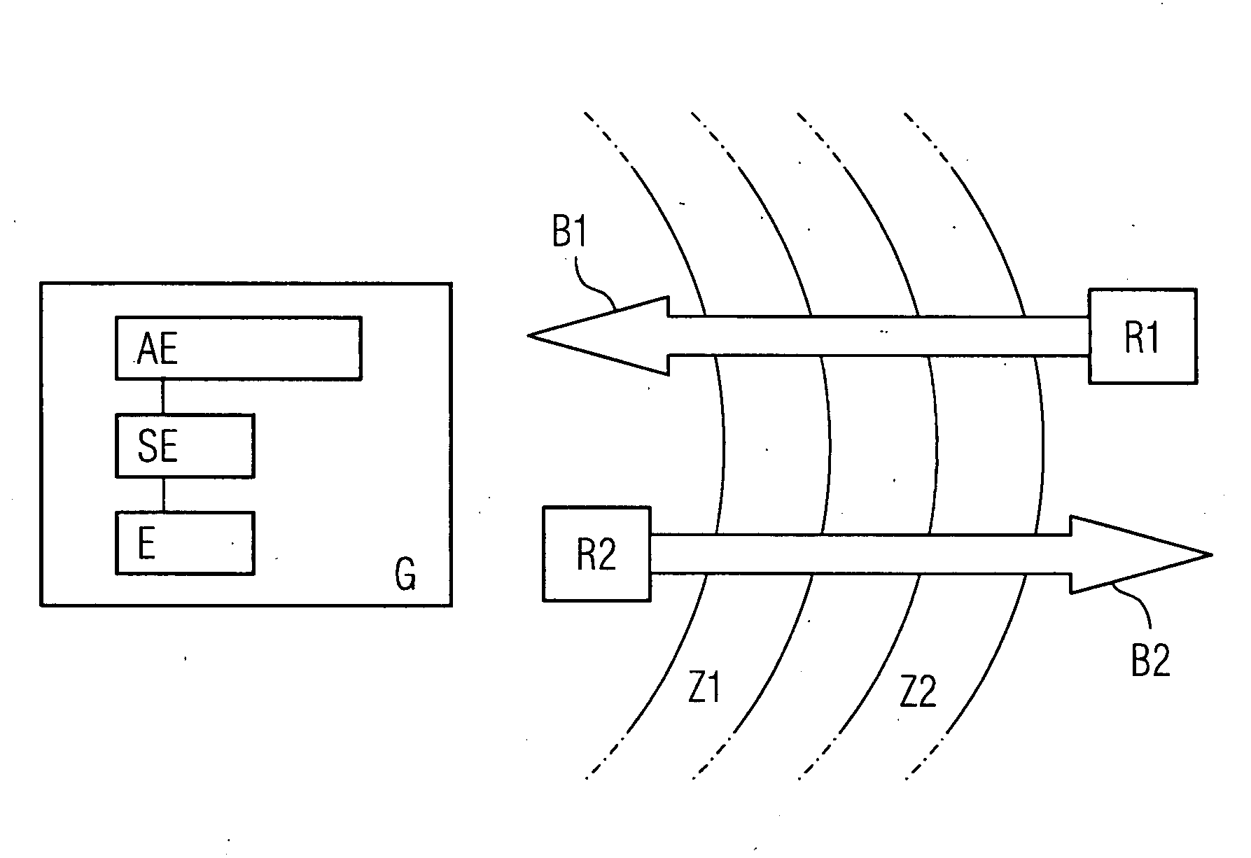
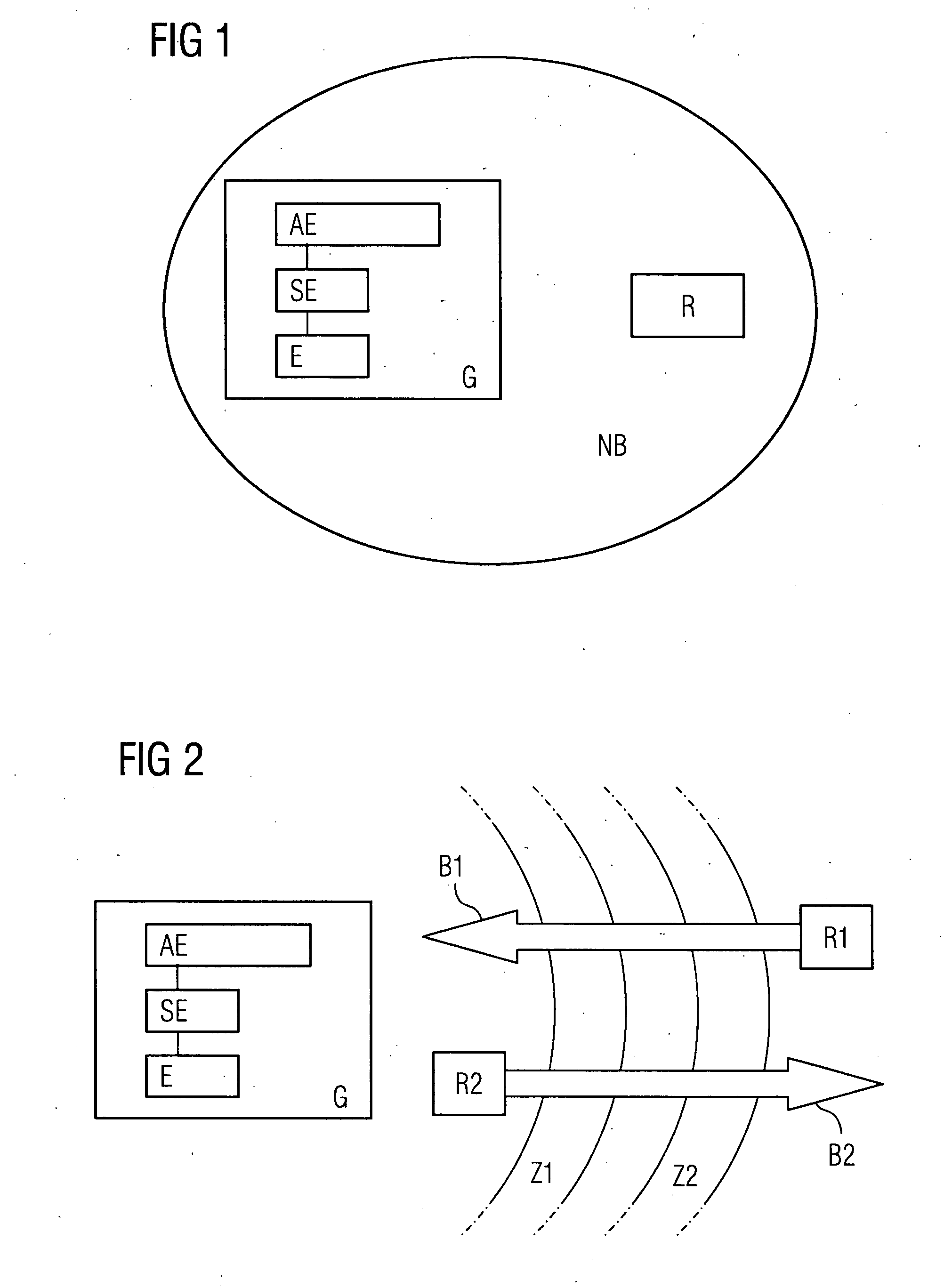
[0028]As one example of an appliance, FIG. 1 shows a communication terminal G which has a display device AE, a control device SE and a receiver E. The near field NB of the communication terminal G is located around the communication terminal G, with the near field in this exemplary embodiment being identical to the reception area of the receiving device E. In this exemplary embodiment, the near field NB is an area with a radius of several meters around the communication terminal G, with this distance being at least as large as the maximum reading distance for the display device AE. A user who is carrying a radio-frequency identification transponder (“RFID-TAG”) R is located in the near field of the communication terminal G.

[0029]In this case, the display device AE comprises a large number of organic light-emitting diodes (so-called OLEDs) which are combined to form an alpha numeric display in a film structure. Other display devices may, of course, also be used instead of the OLED-ba...


PUM


Abstract

There is described a method for operating a device comprising a display device, a communication device and a communication system. According to said method, the display device is activated once a user enters a near field of the device, and the display device is deactivated once a user leaves the near field of the device. The display device comprises OLEDs or other components that have a short service life and / or a high power requirement. Activation and / or deactivation are controlled by a transponder, e.g. an RFID-TAG to be carried by the user, which responder is detected in the near field of the device. Temporary deactivation of the display device can prolong the service life of the display device and / or save power and the use of contactless RFID-TAGs increases ease of operation. The technology can also be used for other purposes, e.g. user authorization.

Description

CROSS REFERENCE TO RELATED APPLICATIONS[0001]This application is the US National Stage of International Application No. PCT / EP2006 / 060166, filed Feb. 22, 2006 and claims the benefit thereof. The International Application claims the benefits of German application No. 10 2005 014 675.9 DE filed Mar. 29, 2005, both of the applications are incorporated by reference herein in their entirety.FIELD OF INVENTION[0002]The invention relates to a method for operation of an appliance having a display device, to a communication terminal having a display device, and to a communication arrangement.BACKGROUND OF INVENTION[0003]Modern communication terminals generally have display devices (displays) by means of which the user can be offered a wide range of information, for example about communication partners, callers, call data, names, the date, the time, etc. Furthermore, the display devices are also used for interactive user guidance, for example by displaying selection menus.[0004]The display de...

Claims


Application Information

Patent Timeline
IPC IPC(8): H04B1/38H04Q5/22
CPCG06F1/3203G06F1/3231H04M1/66Y02B60/50H04W52/027Y02B60/1289H04M1/7253Y02D10/00Y02D30/70H04M1/72412
Inventor BRIESKORN, JURGEN
Owner SIEMENS AG
Learn More