Test structures of a semiconductor device and methods of forming the same

a technology of semiconductor devices and structures, applied in semiconductor/solid-state device testing/measurement, instruments, photomechanical equipment, etc., can solve the problems of reducing the reliability of semiconductor devices and the low integration degree of semiconductor devices, so as to reduce the area, reduce the effect of etching damage to circuit patterns and higher integration degr

Inactive Publication Date: 2009-01-22
SAMSUNG ELECTRONICS CO LTD
View PDF3 Cites 9 Cited by
  • Summary
  • Abstract
  • Description
  • Claims
  • Application Information

AI Technical Summary

Benefits of technology

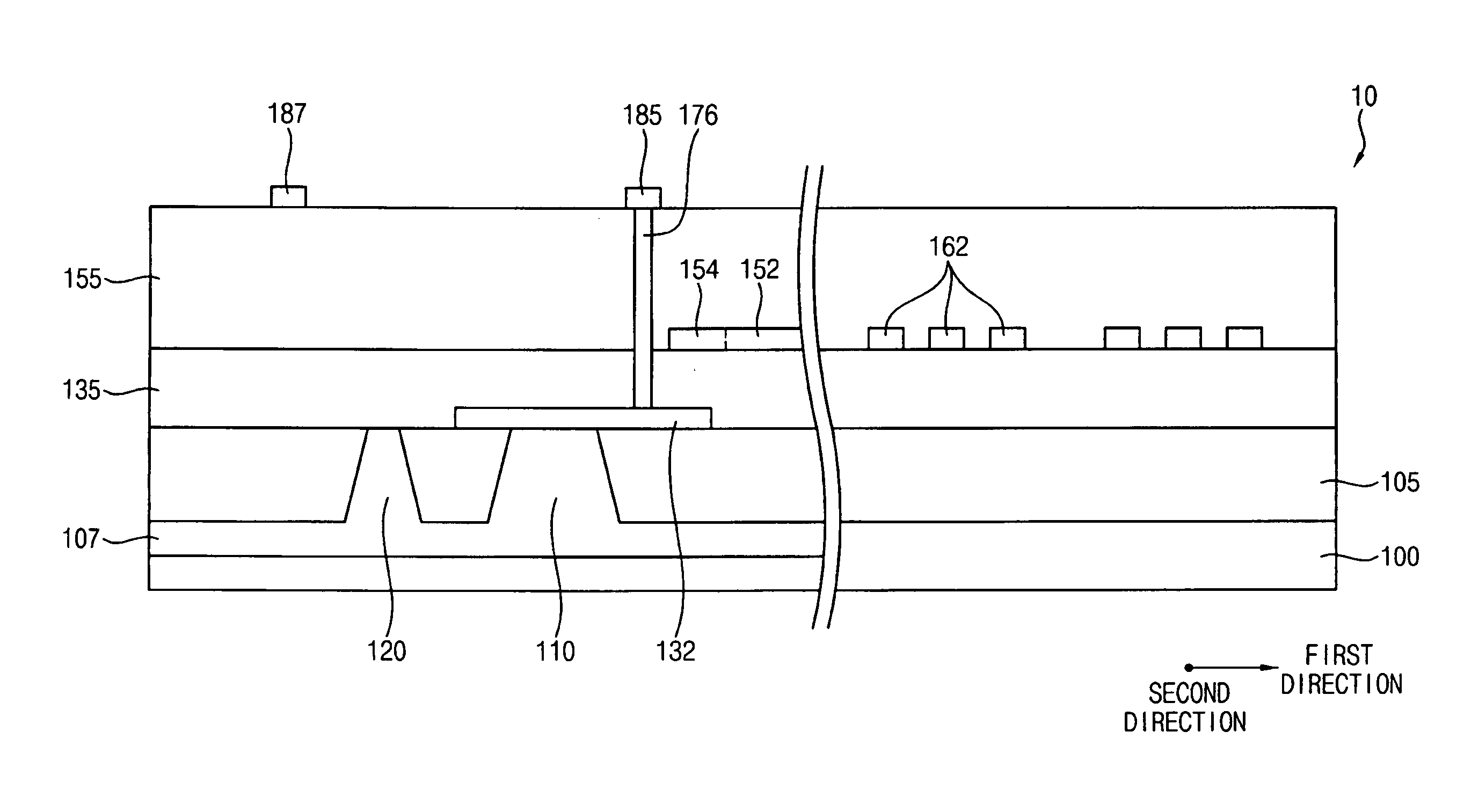
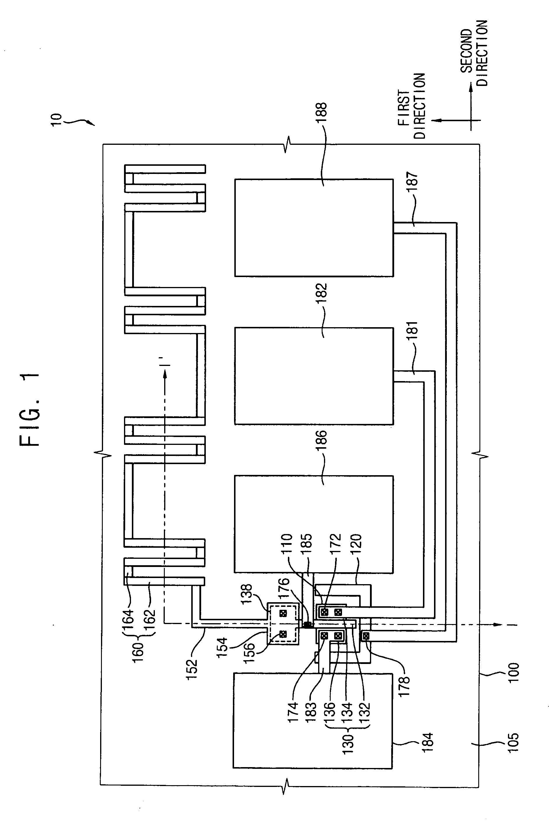
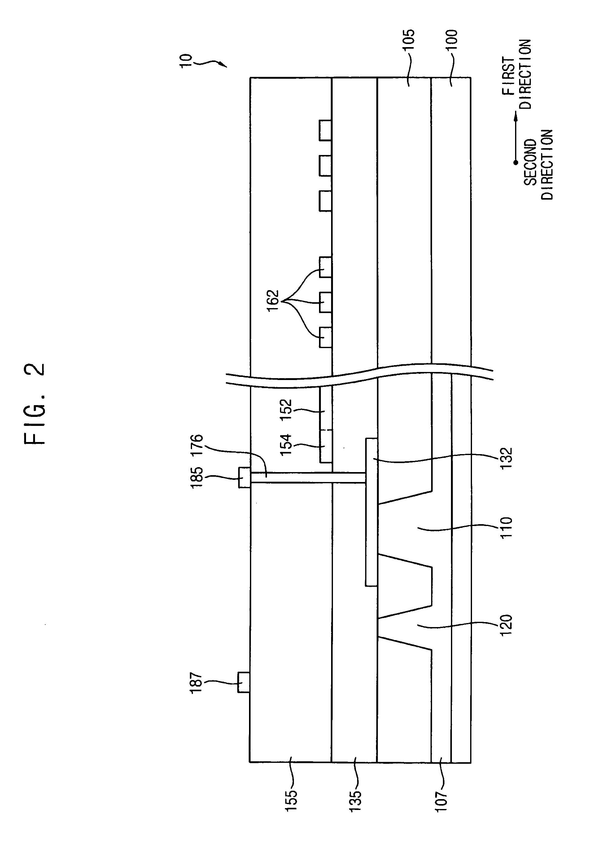
[0031]According to example embodiments, a conductive pattern included in a test structure of a semiconductor device may serve (or function) not only as an antenna for sensing plasma damage to the semiconductor device, but also as an align / overlay pattern for aligning various circuit patterns on the net die region. The conductive pattern may serve (or function) as a dummy pattern for reducing etching damage to the circuit patterns. Thus, a scribe lane region of a substrate, on which the test structure, the align / overlay pattern and the dummy pattern are formed, may have a reduced area such that the semiconductor device including the elements on the scribe lane region may have a higher integration degree. If the test structure, the align / overlay pattern and the dummy pattern are formed on a net die region of the substrate, the net die region may have a relatively reduced area such that the semiconductor device may have a higher integration degree.

Problems solved by technology

However, if the high density plasma process is performed, a substantially strong magnetic field is generated between a substrate and a gate structure.
The strong magnetic field damage a gate insulation layer in the gate structure, thereby reducing the reliability of the semiconductor device.
As such, the semiconductor device may not have a high integration degree.

Method used


Image

  • Test structures of a semiconductor device and methods of forming the same
  • Test structures of a semiconductor device and methods of forming the same
  • Test structures of a semiconductor device and methods of forming the same

Examples


Embodiment Construction

[0043]Various example embodiments will now be described more fully with reference to the accompanying drawings in which some example embodiments are shown. In the drawings, the thicknesses of layers and regions may be exaggerated for clarity.

[0044]Detailed illustrative embodiments are disclosed herein. However, specific structural and functional details disclosed herein are merely representative for purposes of describing example embodiments. This invention, however, may be embodied in many alternate forms and should not be construed as limited to only example embodiments set forth herein.

[0045]Accordingly, while example embodiments are capable of various modifications and alternative forms, embodiments thereof are shown by way of example in the drawings and will herein be described in detail. It should be understood, however, that there is no intent to limit example embodiments to the particular forms disclosed, but on the contrary, example embodiments are to cover all modification...


PUM


Abstract

A test structure including a transistor, a conductive pattern and a pad unit is provided. The transistor may be formed on a substrate having circuit patterns. The conductive pattern is electrically connected to the transistor. The conductive pattern may be used in aligning the circuit patterns and/or sensing plasma damage to the semiconductor device. The conductive pattern may be used in reducing etching damage to the circuit patterns and sensing plasma damage to the semiconductor device. The pad unit is electrically connected to the transistor, and provides electrical signals to the transistor. The conductive pattern may serve as an antenna pattern and/or an align/overlay pattern or a dummy pattern.

Description

PRIORITY STATEMENT[0001]This application claims the benefit of priority under 35 USC §119 to Korean Patent Application No. 2007-72720, filed on Jul. 20, 2007 in the Korean Intellectual Property Office (KIPO), the contents of which are herein incorporated by reference in their entirety.BACKGROUND[0002]1. Field[0003]Example embodiments relate to test structures of a semiconductor device and methods of forming the same. Other example embodiments relate to test structures of a semiconductor device for measuring plasma damage to the semiconductor device and methods of forming the same.[0004]2. Description of the Related Art[0005]In a method of manufacturing a semiconductor device, a photolithography technique may be necessary. The photolithography technique includes etching processes (e.g., a plasma etching process, a reactive ion etching (RIE) process or similar processes). Due to the higher integration degree of semiconductor devices, plasma etching processes (e.g., a high density plas...

Claims


Application Information

Patent Timeline
Patent Type & Authority Applications(United States)
IPC IPC(8): H01L23/58H01L21/84
CPCH01L22/34H01L2924/0002H01L2924/00G03F7/70608G03F7/70616H01L21/0274H01L21/30655
Inventor LEE, JAE-PIL
Owner SAMSUNG ELECTRONICS CO LTD
Why Eureka
Try Eureka