

Image Processor and Endoscope Apparatus
a technology of endoscope and image processor, which is applied in the field of image processor and endoscope apparatus, can solve the problems of insufficient light intensity and easy to notice noise, and achieve the effect of suppressing noise in the dark image area and avoiding the reduction of the contrast in the bright image area
- Summary
- Abstract
- Description
- Claims
- Application Information
AI Technical Summary
Benefits of technology
Problems solved by technology
Method used
Image

Examples
first embodiment
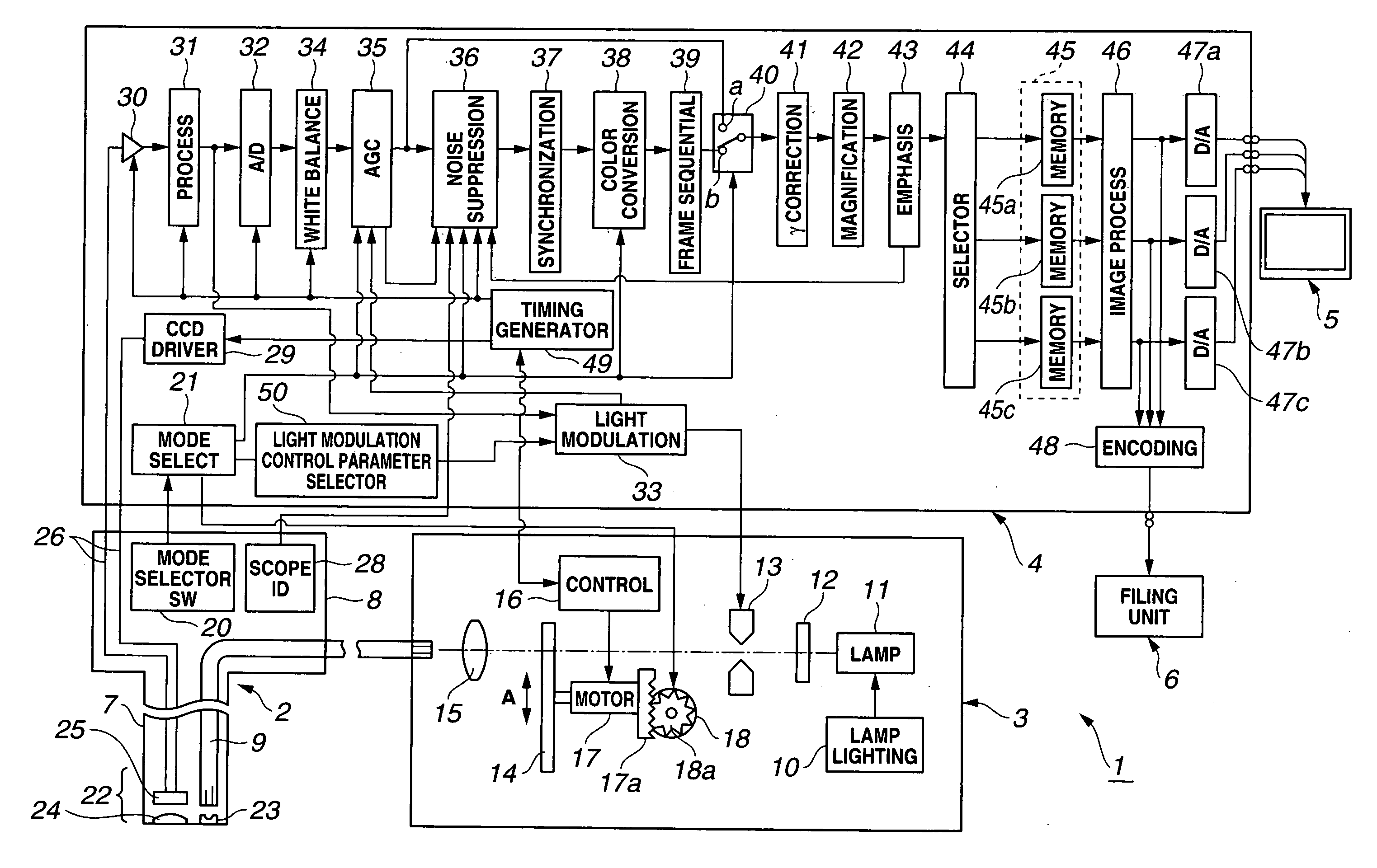
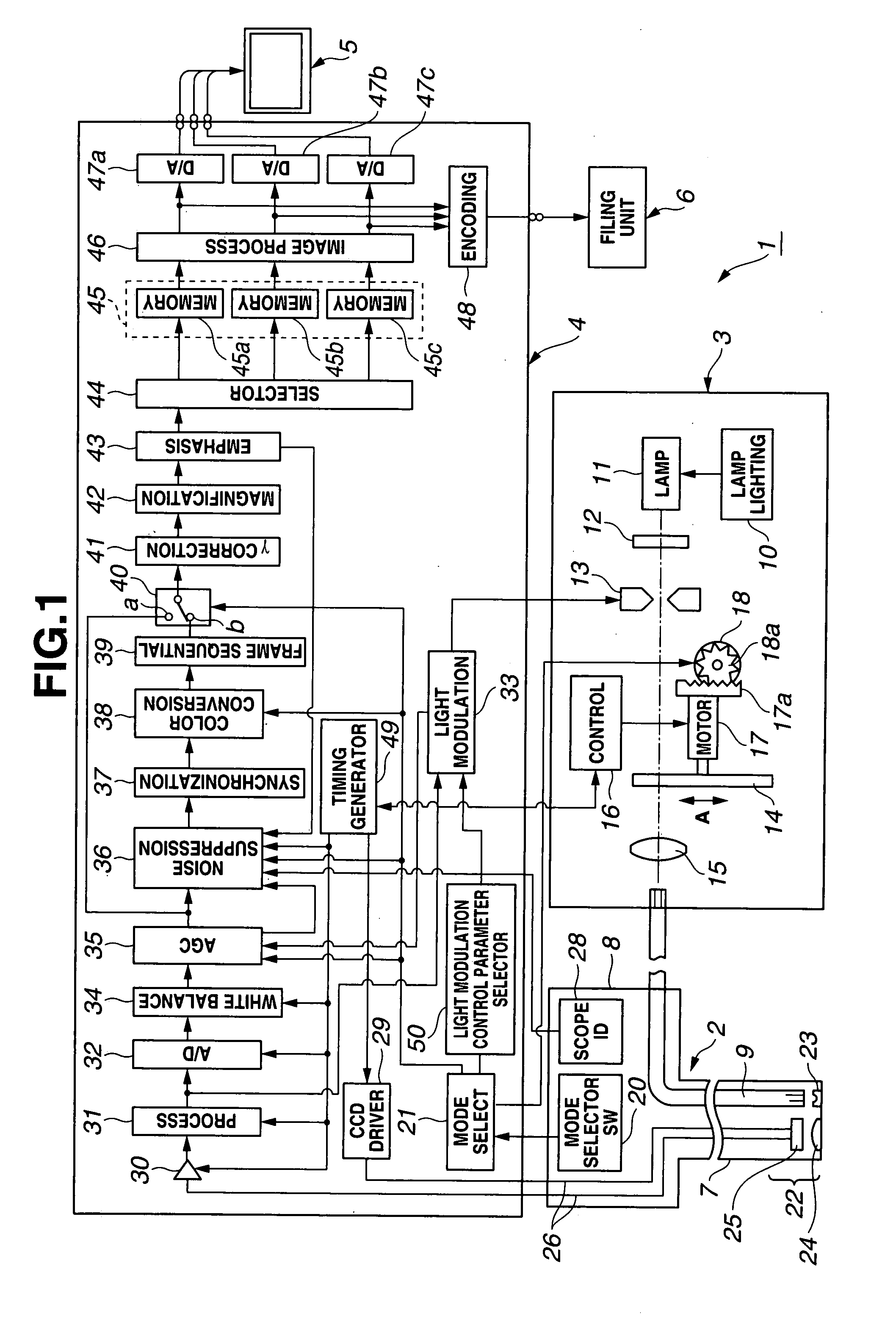
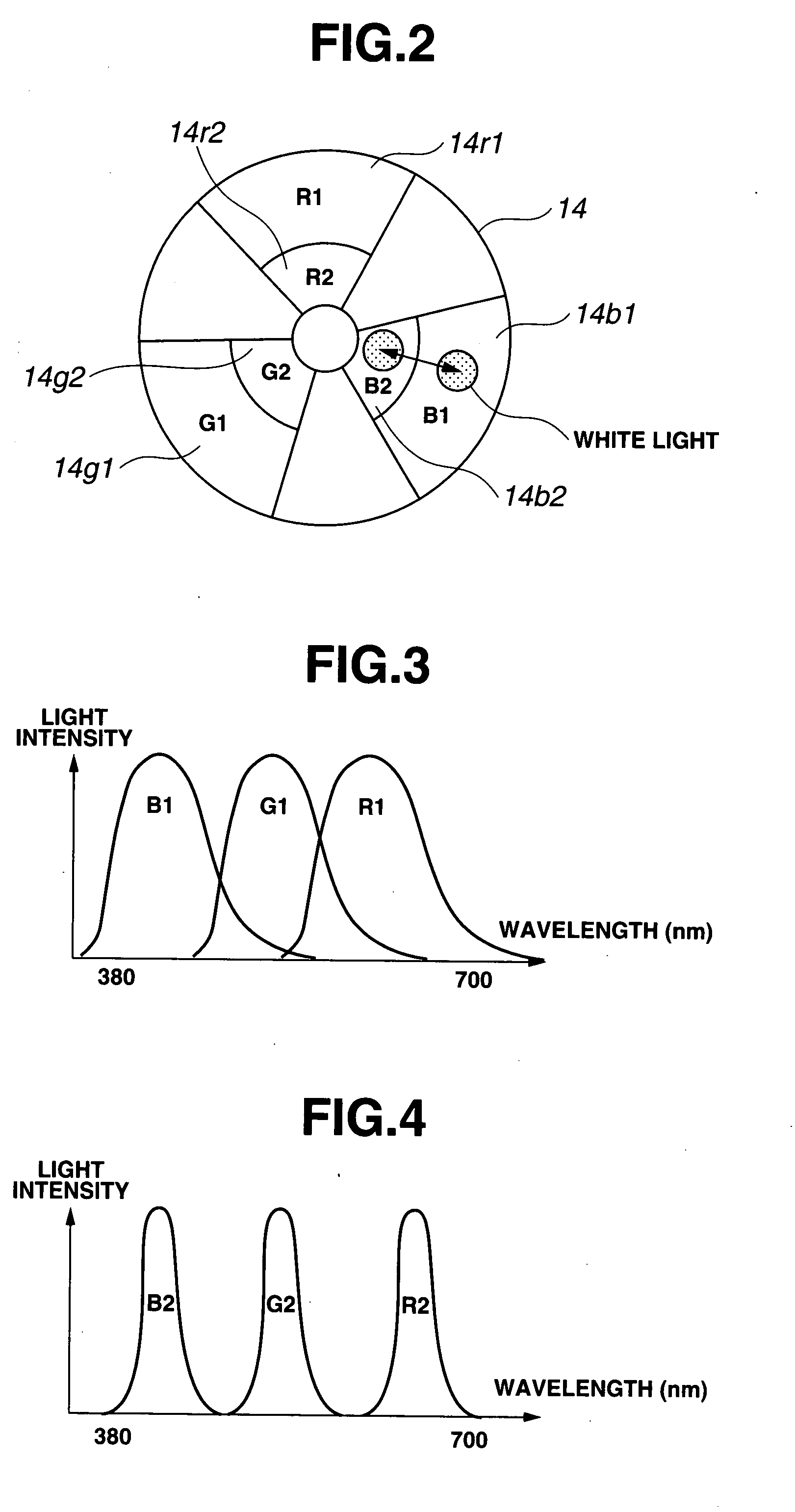
[0045]FIGS. 1 to 10 show the first embodiment of the present invention. FIG. 1 is a view showing an entire configuration of an endoscope apparatus equipped with a first embodiment of the present invention. FIG. 2 is a view showing a configuration of a rotary filter shown in FIG. 1. FIG. 3 is a view showing a spectroscopic characteristic of a first filter group of the rotary filter shown in FIG. 2. FIG. 4 is a view showing a spectroscopic characteristic of a second filter group of the rotary filter shown in FIG. 2. FIG. 5 is a diagram showing a configuration of a noise suppression circuit.
[0046]FIG. 6 is a view showing a characteristic example of a weighting coefficient to the filter process result. FIG. 7 is a view showing a function example of a threshold value that determines the characteristic of the weighting coefficient to the mean value of the pixel value in the local area. FIG. 8 is an explanatory view of a noise suppressing function in the present embodiment. FIG. 9 is an ex...
second embodiment
[0154]A second embodiment according to the present invention will be described referring to FIG. 11. The present embodiment is formed by modifying the first embodiment. The present embodiment is intended to effectively suppress noise in the case where the electronic endoscope equipped with different type of image pickup means is connected, or the outline or the structure emphasis level is changed.
[0155]In the first embodiment, the noise suppression circuit 36 is commonly used independent from the type of the CCD 25. In the present embodiment, the weighting coefficient is changed in the weighting section depending on the type of the CCD 25, the gain value of the AGC circuit 35 which is set in the operation state (AGC ON), and the emphasis level of the emphasis circuit 43. The other configuration is the same as that of the first embodiment.
[0156]FIG. 11 shows the configuration of the circuit around the noise suppression circuit 36 in the second embodiment. Likewise the first embodimen...
third embodiment
[0186]A third embodiment of the present invention will be described referring to FIGS. 16 to 19. The present embodiment is intended to improve the noise suppressing function while suppressing the circuit size.
[0187]In the present embodiment, the weighted mean is performed with respect to the output of the inverse filter process and the original pixel value using the output value of brightness in the first or the second embodiment.
[0188]FIG. 16 shows the configuration of the circuit around the noise suppression circuit in the third embodiment. The present embodiment employs a noise suppression circuit 36′ including a filter section 51′ with the larger filter size than that of the filter section 51 in the noise suppression circuit 36 in the first embodiment.
[0189]When the filter size is increased to make the frequency resolution high, the noise suppression effect may be improved, but the circuit size is increased.
[0190]For the purpose of providing the pixel value before the process th...
PUM
 Abstract
Description
Claims
Application Information