Automatically adjusting multi-media scanner

Active Publication Date: 2009-01-22
VISIONEER INC A WHOLLY OWNED SUBSIDIARY OF SOQUE HOLDIN
View PDF15 Cites 6 Cited by
  • Summary
  • Abstract
  • Description
  • Claims
  • Application Information

AI Technical Summary

Benefits of technology

[0009]When the motor starts, the cantilever system causes the roller to initially and momentarily drop to accept the media based upon its thickness and the roller continues to rotate and pull the media through. A second spring connected to the CIS will adjust to the thickness of the media and insure consistent pressure/angle resulting in consistent imaging throughout the scan path. The CIS begins at an angle and follows the media perpendicular to it throughout the scan process as it rotates from a fixed point. As the motor begins to turn the gears, the lower spring is depressed, and the energy becomes stored in the spring which allows for the momentary lowering of the roller, return, and subsequent “grabbing” of the media. As a result, a smaller motor than the present art scanners is acceptable as the reliance is not solely on the motor to complete the drawing process. The friction with the CIS is overcome due to the cantilever system creating a gap thereby making a smaller, and less expens

Problems solved by technology

This construction is limited in that media tends to get stuck in the scanner when the thickness cannot be accommodated by such a process.
Fur

Method used


Image

  • Automatically adjusting multi-media scanner
  • Automatically adjusting multi-media scanner
  • Automatically adjusting multi-media scanner

Examples


Example

[0014]The following detailed description illustrates the invention by way of example, not by way of limitation of the principles of the invention. This description will clearly enable one skilled in the art to make and use the invention, and describes various embodiments, adaptations, variations, alternatives, and uses of the invention. The description includes what are presently believed to be the best modes of carrying out the invention.

[0015]In this regard, the invention is illustrated in 2 relatively simple figures; although sufficiently complex as to illuminate to one skilled in the art of such scanner architecture, and calibration methods viable for making or using said invention.

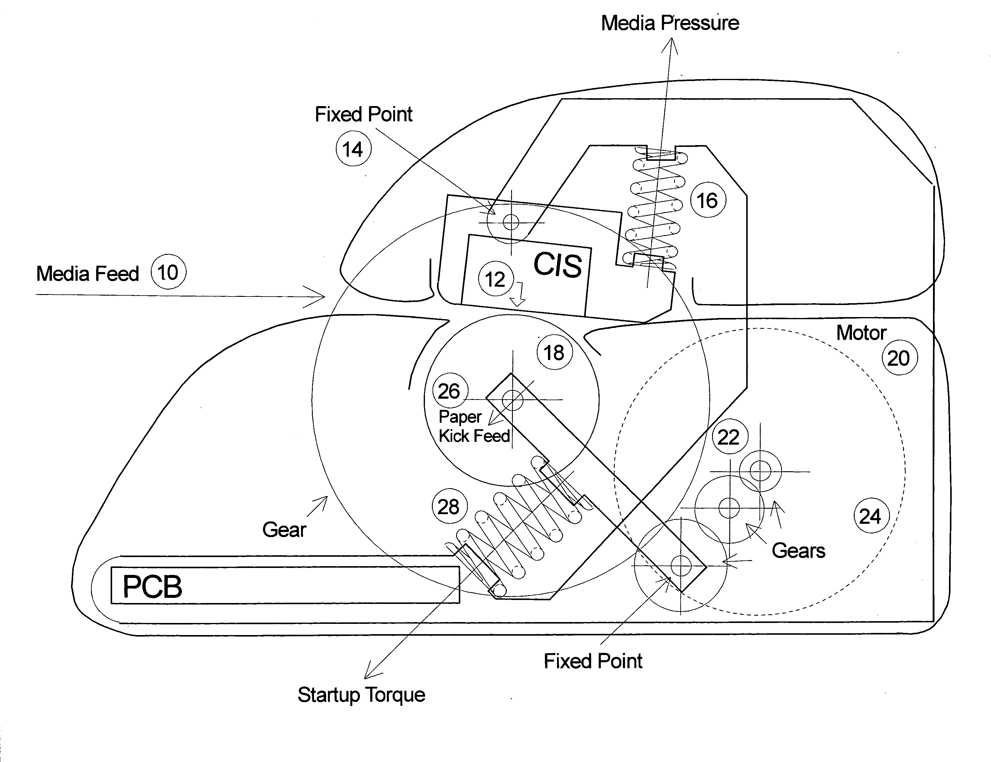
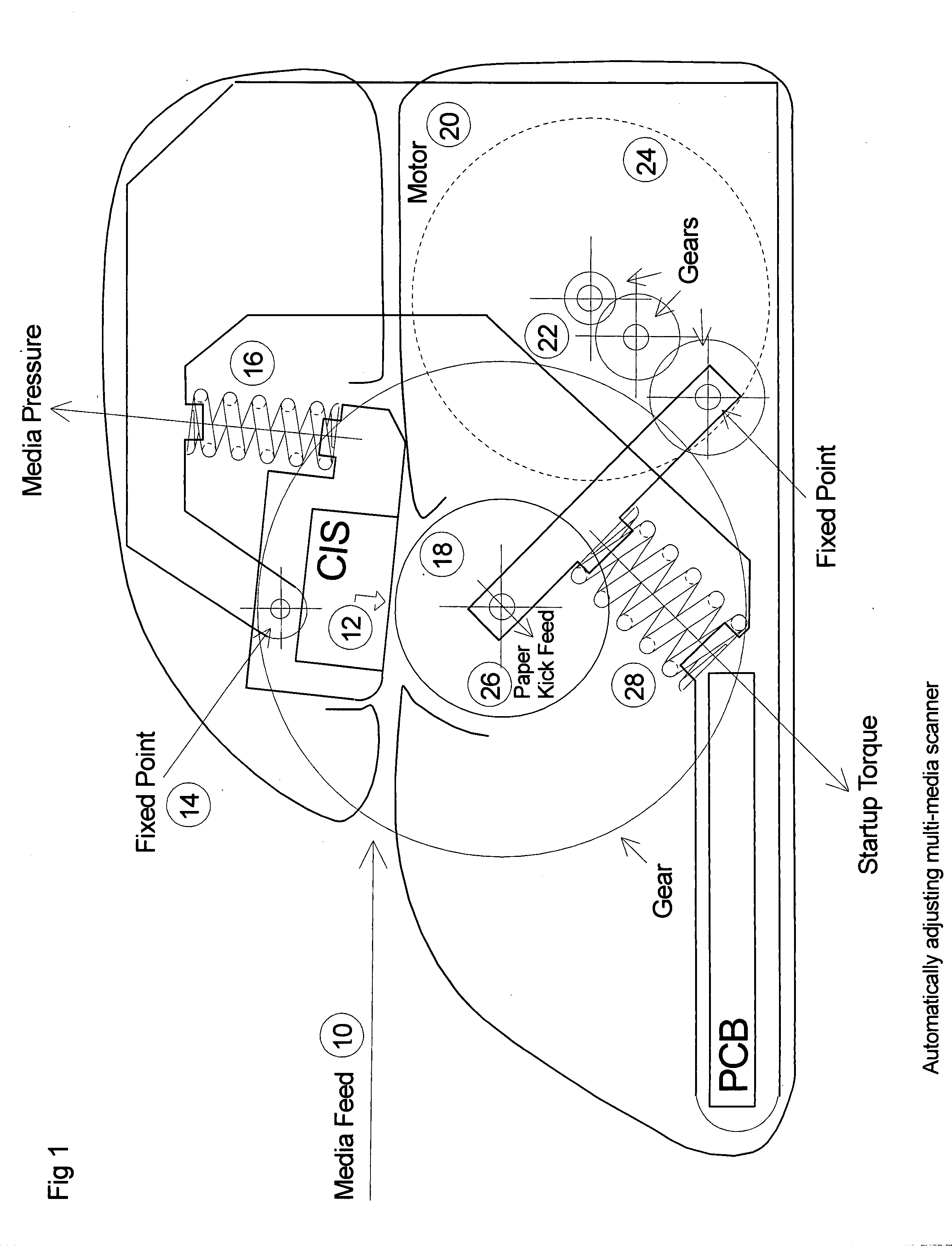
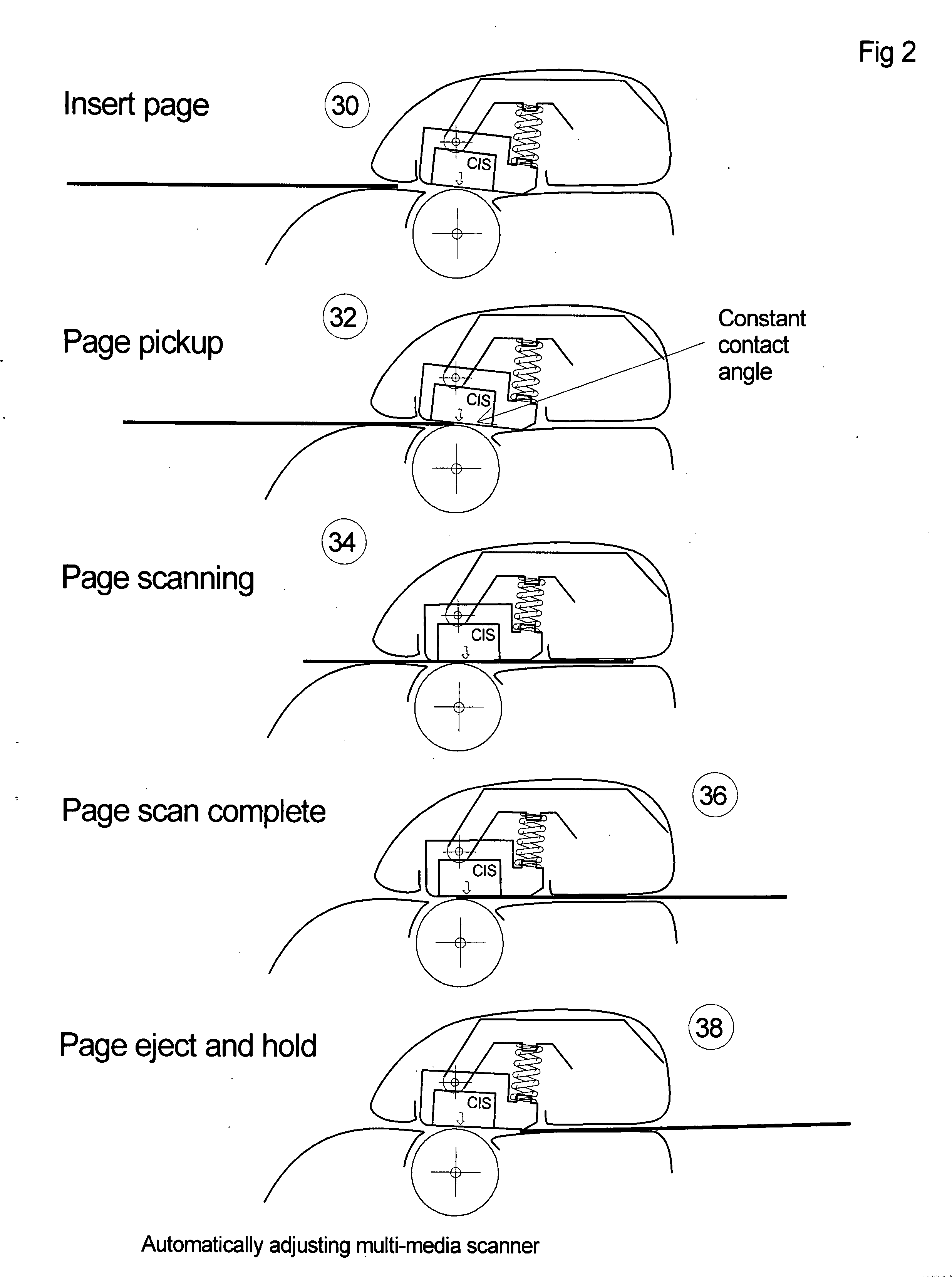
[0016]FIG. 1 illustrates the inventive apparatus as a side transparent view. The media feed 10 leads into the CIS 12, which is affixed at a fixed point 14 connected to a spring loaded upper and lower attachment point. Upon media insertion by a user, the CIS 12 which begins at an angle, will rotate to ...


PUM


Abstract

The invention claimed is a scanner which allows for any type of media, including embossed credit cards, with a thickness in the range of 0.1 mm to 1.5 mm to be inserted into the media path and remain in constant contact with the CIS as a result of a spring loaded roller, gear, and cantilever system. The input process, called a “kick start” method, allows for momentary lowering of the roller, and return, as it spins to grasp the media and continue pulling said media through the scan path. This apparatus stores energy provided by the motor within its spring and gear system, thus requiring less energy from the motor, and reduces manufacturing costs.

Description

FIELD[0001]The invention relates to digital document scanners, and more particularly to a scanner which automatically adjusts for and accepts a variety of media thicknesses while optimizing the media's contact with the CIS throughout the imaging process and utilizing the energy produced by a gear / spring system to reduce the need for a large motor.BACKGROUND OF THE INVENTION[0002]The invention most closely corresponds with USPTO Class 358, wherein the invention involves the communication or reproduction of a static image or sequence of static images in which the density variations composing the image do not vary with time (e.g., a document image) by a method or apparatus.[0003]In its simplest form, the invention comprises a document scanner wherein the hardware allows for a variety of media thicknesses to be scanned without user adjustment, and wherein the CIS remains in constant contact with the media. This invention may be utilized in both simplex and duplex modes.[0004]With curren...

Claims


Application Information

Patent Timeline
IPC IPC(8): H04N1/03
CPCH04N1/00827H04N1/193H04N1/1215
Inventor OS, RON VAN
Owner VISIONEER INC A WHOLLY OWNED SUBSIDIARY OF SOQUE HOLDIN
Why Eureka
Try Eureka