
Multi-level electronic protection system providing safe fault recovery for multiple digital control outputs

Active Publication Date: 2009-01-22
HONEYWELL INT INC
View PDF2 Cites 21 Cited by
  • Summary
  • Abstract
  • Description
  • Claims
  • Application Information

AI Technical Summary

Benefits of technology

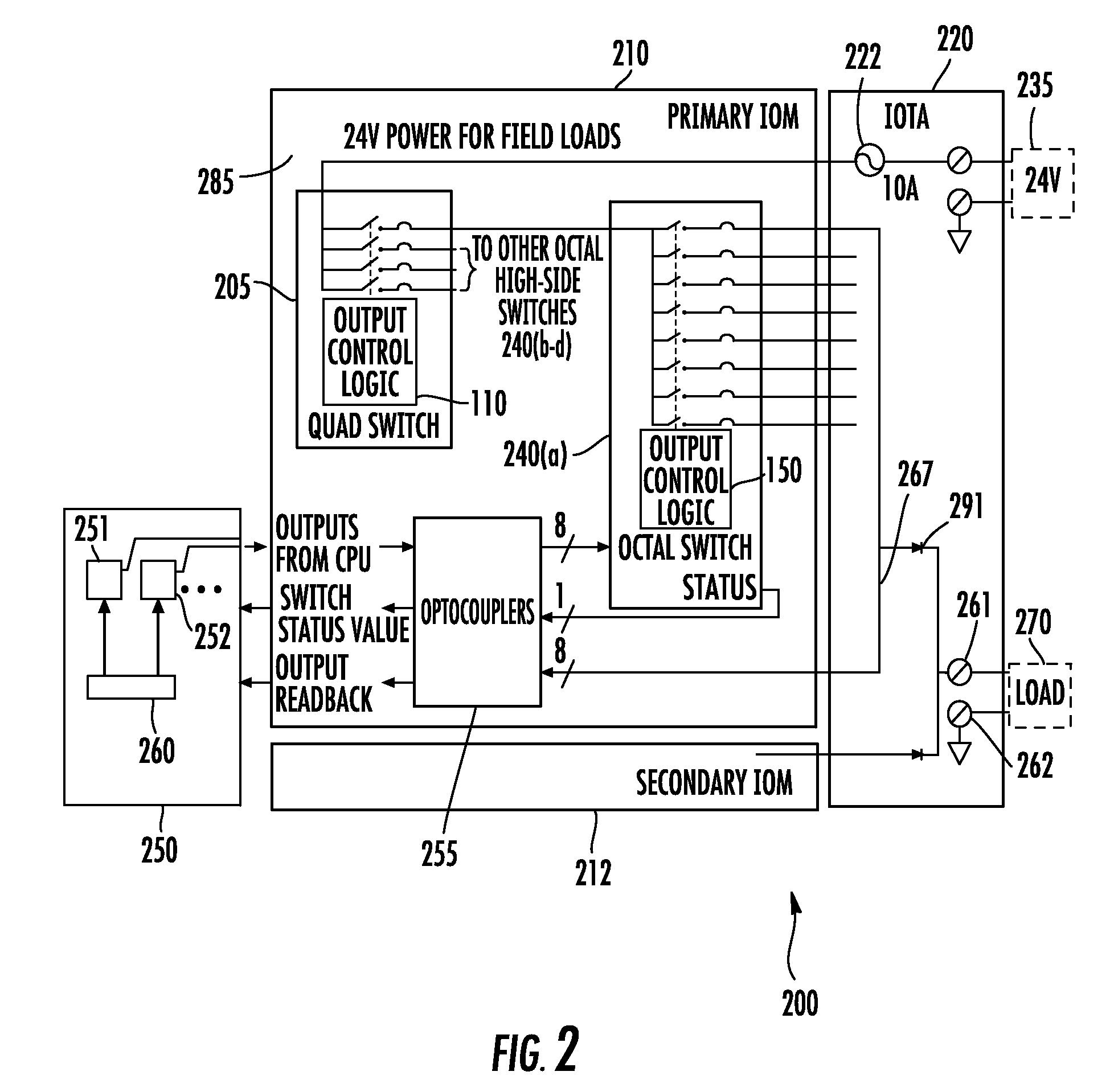
[0007]In a preferred embodiment, the system further comprises an isolation device and CPU having associated firmware coupled to the second output channels and the external inputs of the second switches via the isolation device. In this embodiment, the isolation device can comprise a multi-channel optocoupler. The CPU can includes a plurality of status registers. One of the status registers can be associated with each of the plurality of second output channels. In one embodiment, the firmware is operable for monitoring a state of each of the plurality of second output channels, wherein the firmware compares a state of each of the plurality of second controlled outputs to at least one predetermined reference level and causes the status registers to provides a turn off signal to the external inputs of the second switching device to disable any of said second output channels responsive to a determination of a faulted output by said firmware. This arrangement can eliminate oscillation of outputs between being ON and OFF that can otherwise occur. In one embodiment, the current limits for each of the first output channels is greater than the current limits for groups of the second output channels associated with each of the first output channels.

Problems solved by technology

Active current limitation is combined with thermal shutdown and automatic restart, which protects the device against overload.

Method used


Image

  • Multi-level electronic protection system providing safe fault recovery for multiple digital control outputs
  • Multi-level electronic protection system providing safe fault recovery for multiple digital control outputs
  • Multi-level electronic protection system providing safe fault recovery for multiple digital control outputs

Examples


Embodiment Construction

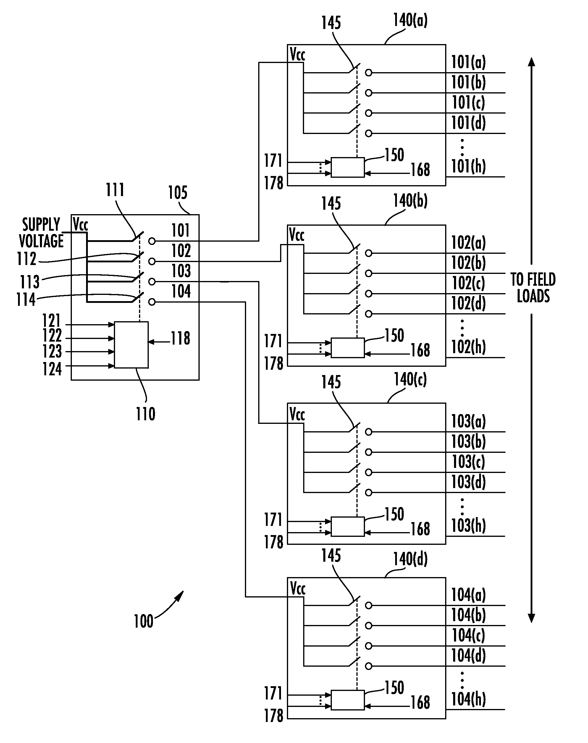
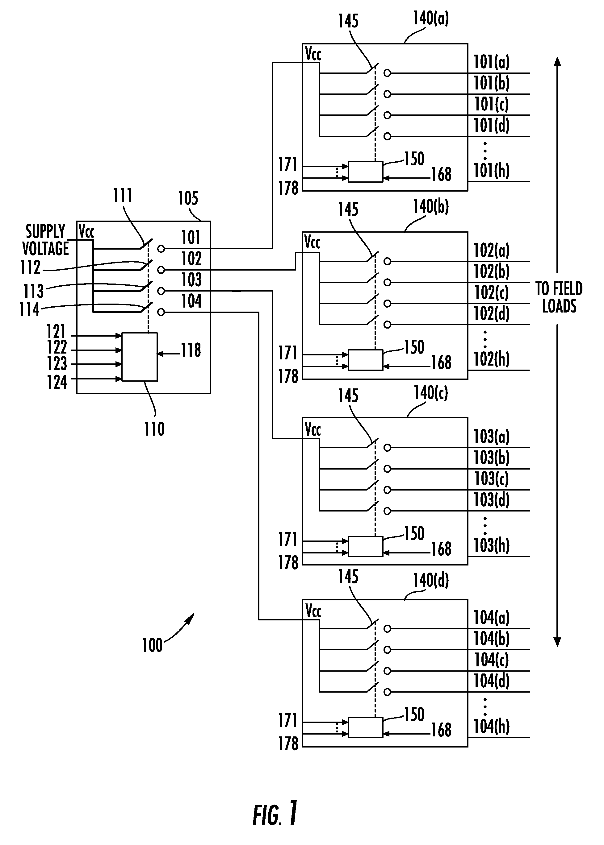
[0012]This present invention provides multi-level short circuit and / or over current protection for a plurality of digital control outputs (DOs) without the need for operator intervention. The protection is configured to be channel independent, such that a fault in one output channel does affect the other channels. The protection is provided by solid state reversibly interruptible electronic switching devices which provide “reversibly interruptible” performance, defined herein as a sensing arrangement or mechanism (unlike a conventional fuse) that interrupts power and automatically permits a return to normal service once the fault is no longer present. Thus, once the fault condition has been detected and subsequently corrected, no further maintenance (e.g. fuse replacement) is required. In a preferred embodiment, the system includes a CPU or other processor having embedded firmware which performs a supervisory function as described below.

[0013]FIG. 1 shows a simplified block diagram ...


PUM


Abstract

A multi-level over-current electronic protection system for protecting a plurality of outputs includes a first solid state reversibly interruptible electronic switch including first output control logic and a plurality of first controlled output channels controlled by the first control logic. The first switching device is coupled to receive power from at least one power supply selected to power a plurality of loads. The first switching device provides power at its plurality of first output channels under normal operating conditions, wherein the first output control logic is operable for reversibly interrupting power at any of the first output channels when current in any of the first output channels exceed limits for the first output channels. At least one second solid state reversibly interruptible electronic switch including second control logic and a plurality of second controlled outputs control by the second control logic is also provided. A power supply input of the second switch is coupled to one of the plurality of first controlled output channels to receive the power, wherein the second controlled outputs are coupled to provide the power to the plurality of loads under normal operating conditions and reversibly interrupting the power for any of the second output channels when current in any of said second output channels exceeds limits for the second output channels. A CPU having associated firmware can be coupled to the second output channels and external inputs of the second switches via an isolation device to provide a supervisory and monitoring function.

Description

FIELD OF THE INVENTION[0001]The present invention relates to electronic circuit protection systems which protect multiple digital control outputs, such as outputs associated with an industrial process, from short circuits or other potentially destructive conditions.BACKGROUND[0002]In a process control system, a process is controlled which generally involves the monitoring and controlling of fluid flow, fluid flow rate, fluid levels, temperature, pressure, position, or levels (e.g. tank or vat levels). These parameters are resultants of a process and are measured by a variety of field devices including devices such as valves, flow meters, position indicators, and motors. As the process continues, the measured parameters are generally monitored by a CPU-based main controller, and output signals are generated for controlling the various field devices (or field equipment) or interposing control relays that connect to the field devices. In the event of a failure in the system, there is a...

Claims


Application Information

Patent Timeline
IPC IPC(8): H02H3/00
CPCG05B2219/21154G05B19/0425
Inventor FLAY, DUSTINMARTIN, CHARLES L.INGAWALE, SUNIL M.
Owner HONEYWELL INT INC
Learn More