Gas concentration measuring apparatus designed to enhance response of sensor

a technology of measuring apparatus and sensor, which is applied in the direction of measuring devices, instruments, electrochemical variables of materials, etc., can solve the problems of oscillation of the voltage to be applied to the sensor element, and achieve enhanced gain, enhanced response of the sensor element, and avoid the effect of oscillation of the voltag

Inactive Publication Date: 2007-09-20
DENSO CORP
View PDF1 Cites 13 Cited by
  • Summary
  • Abstract
  • Description
  • Claims
  • Application Information

AI Technical Summary

Benefits of technology

[0014]When the total gain of a combination of the sensor element and the applied voltage controller exceeds one (1), it will result in oscillation of the voltage to be applied to the sensor element. The frequency characteristics of the applied voltage controller are, thus, defined to eliminate such oscillation. For example, in the case where the sensor element is equipped with a solid electrolyte layer, it has high-pass filter characteristics as frequency characteristics. The total gain of the sensor element and the applied voltage controller may thus be kept below one (1) by designing the applied voltage controller to have low-pass filter characteristics, thereby avoiding the oscillation of the voltage to be applied to the sensor element.
[0015]The applied voltage controller is, as described above, designed to have the enhanced gain in the desired frequency band, thereby enabling the response of the sensor element to be enhanced without inducing the oscillation of the voltage to be applied to the sensor element.

Problems solved by technology

When the total gain of a combination of the sensor element and the applied voltage controller exceeds one (1), it will result in oscillation of the voltage to be applied to the sensor element.

Method used


Image

  • Gas concentration measuring apparatus designed to enhance response of sensor
  • Gas concentration measuring apparatus designed to enhance response of sensor
  • Gas concentration measuring apparatus designed to enhance response of sensor

Examples


Embodiment Construction

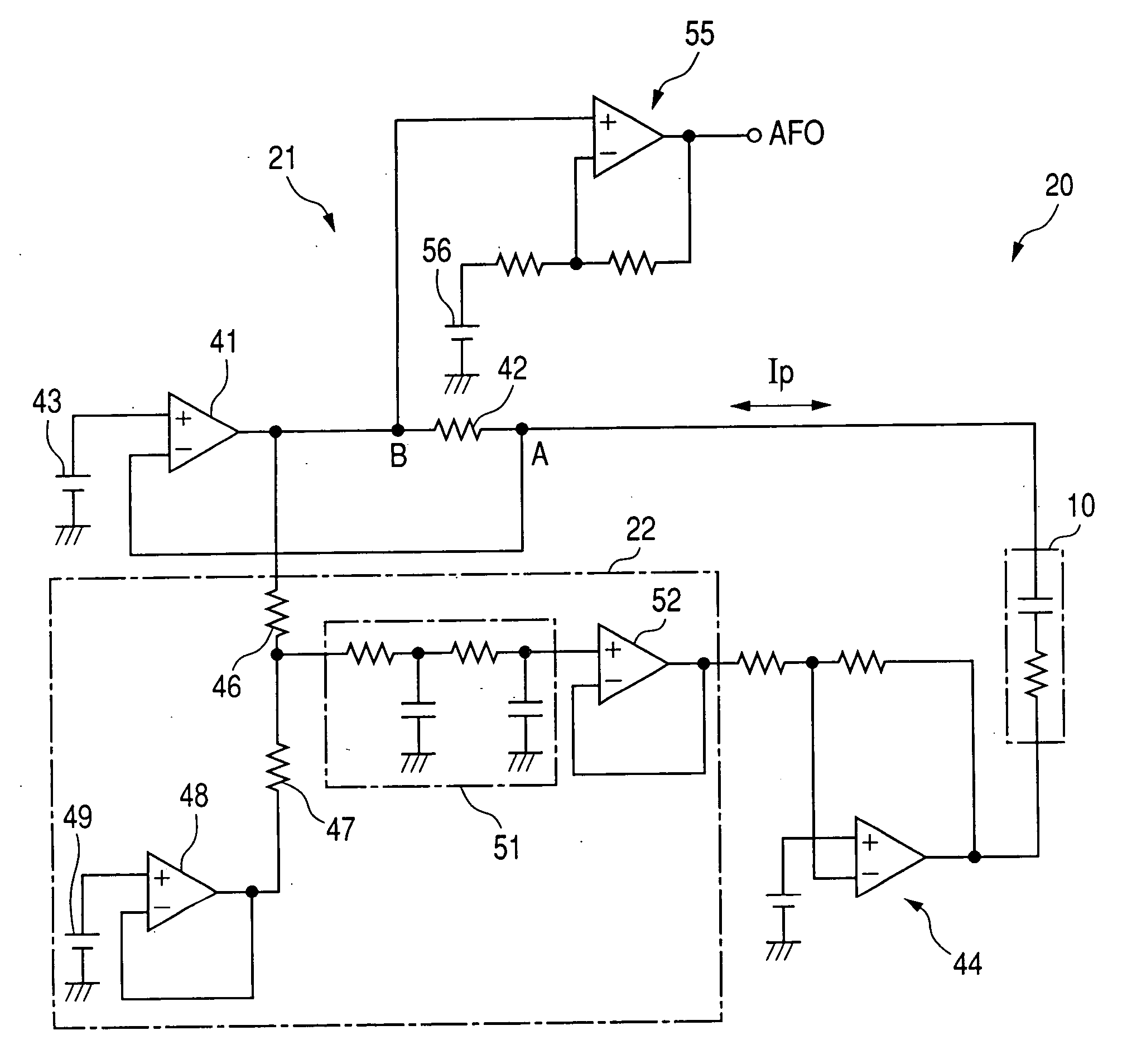
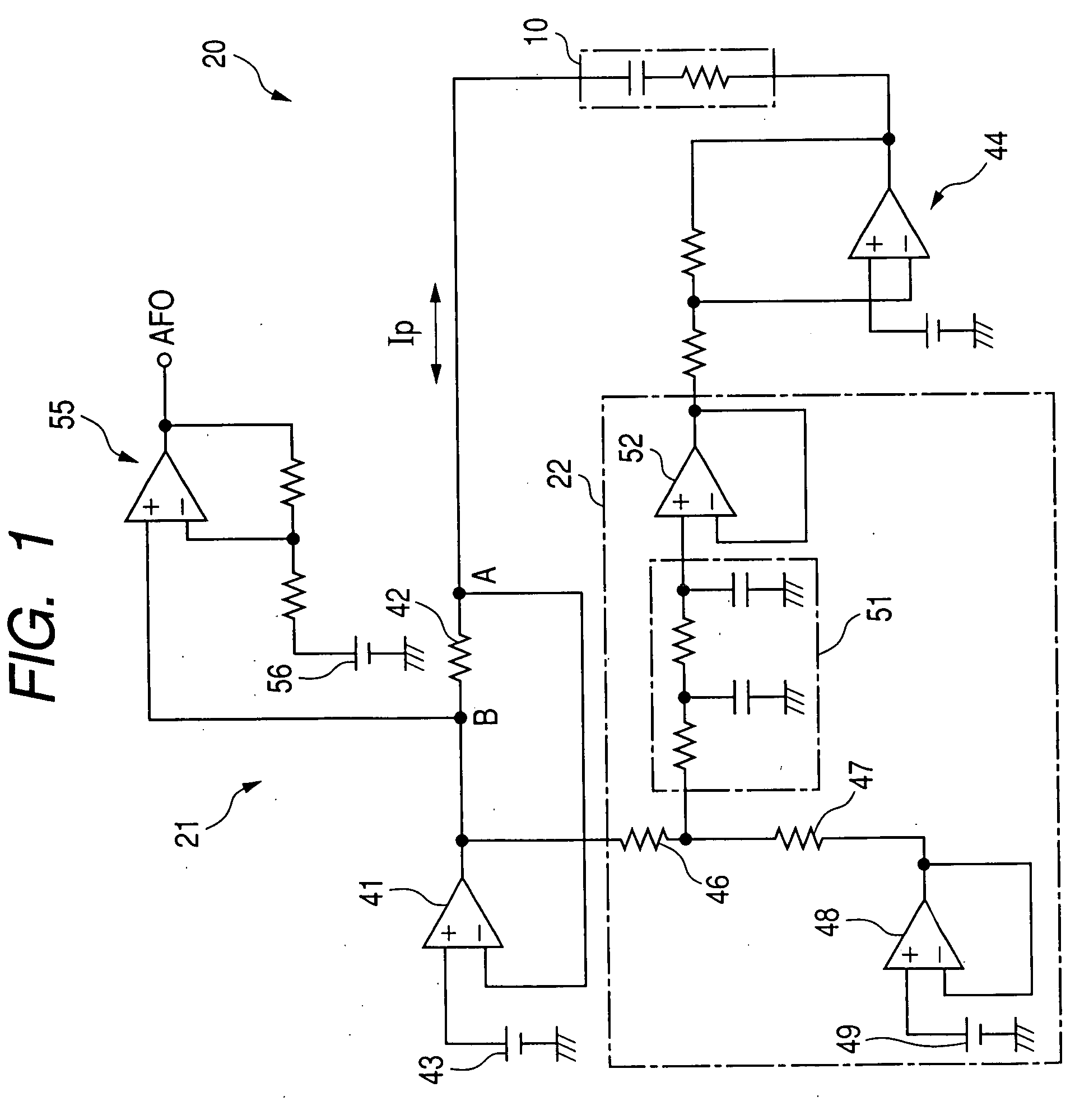
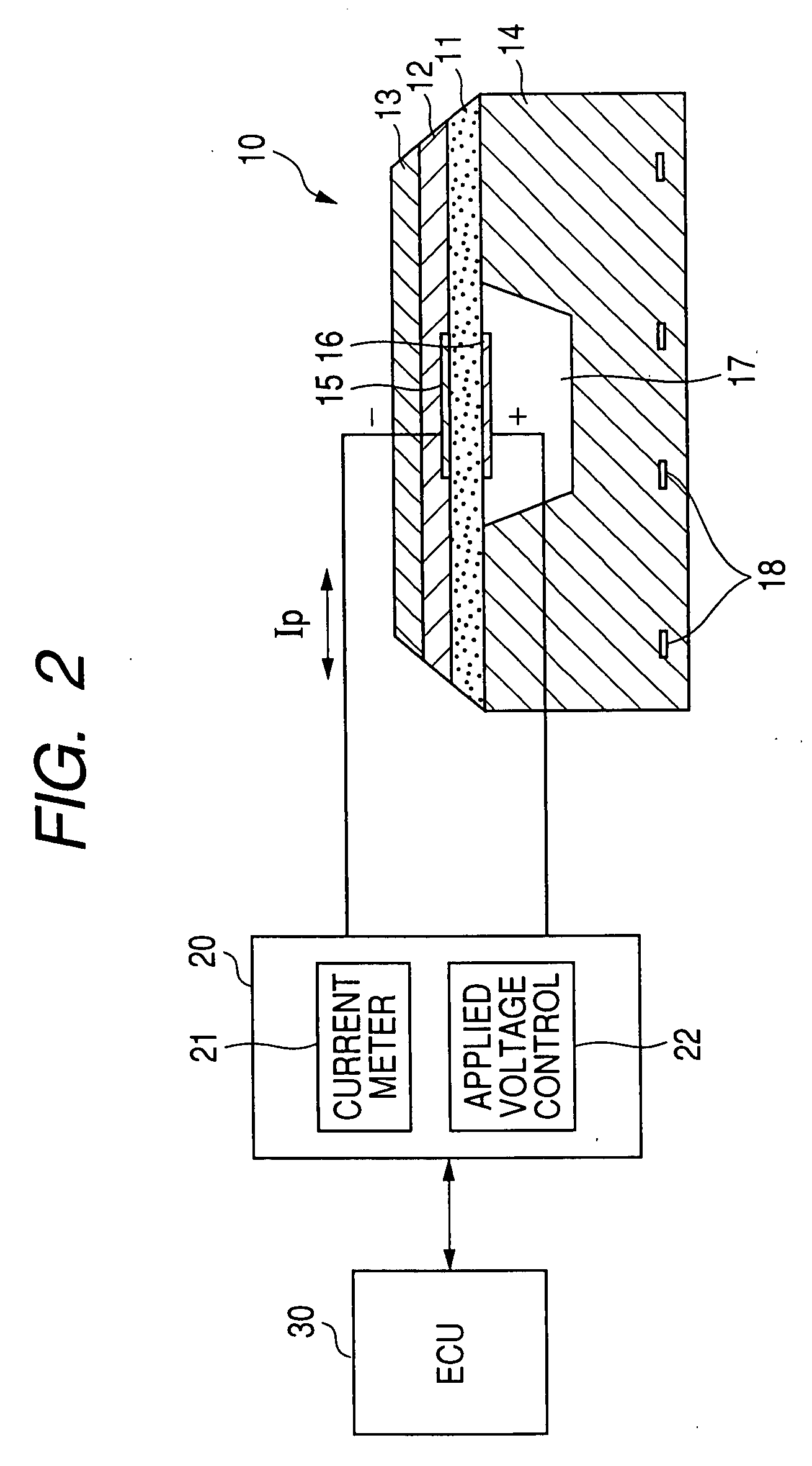
[0037]Referring to the drawings, wherein like reference numbers refer to like parts in several views, particularly to FIGS. 1 and 2, there is shown a gas concentration measuring apparatus designed to measure the concentration of oxygen (O2) contained in exhaust emissions of an automotive engine which corresponds to an air-fuel ratio of a mixture supplied to the engine. The measured concentration is used in an air-fuel ratio control system implemented by an engine electronic control unit (ECU). The air-fuel ratio control system works to perform a stoichiometric burning control to regulate the air-fuel ratio of the mixture around the stoichiometric air-fuel ratio under feedback control and a lean-burn control to bring the air-fuel ratio to within a given lean range under feedback control.

[0038]The gas concentration measuring apparatus, as illustrated in FIG. 2, includes a sensor control circuit 20, an electronic control unit (ECU) 30, and an oxygen sensor (will be referred to as an ai...


PUM

PropertyMeasurementUnit
cut-off frequencyaaaaaaaaaa
frequency side cut-off frequencyaaaaaaaaaa

Abstract

A gas concentration measuring apparatus is provided which may be employed in measuring the concentration of oxygen contained in exhaust emissions of automotive engines. The apparatus includes a gas sensor equipped with a solid electrolyte body and a pair of electrodes affixed to opposed surfaces of the solid electrolyte body. The apparatus includes an applied voltage controller which works to apply the voltage to the electrodes of the gas sensor to create an electric current as a function of a concentration of gas to be measured. The applied voltage controller is designed to have an enhanced gain of the voltage to the value of the current, as produced by the gas sensor, in a predetermined frequency band, thereby increasing the response of the gas sensor without inducing the oscillation of the voltage to be applied to the gas sensor.

Description

CROSS REFERENCE TO RELATED DOCUMENT[0001]The present application claims the benefit of Japanese Patent Application No. 2006-69011 filed on Mar. 14, 2006, the disclosure of which is totally incorporated herein by reference.BACKGROUND OF THE INVENTION[0002]1. Technical Field of the Invention[0003]The present invention relates generally to a gas concentration measuring apparatus which may be used in measuring the concentration of a preselected component, such as oxygen, of exhaust emissions of automotive engines, and more particularly to such a gas concentration measuring apparatus designed to enhance the response of a sensor.[0004]2. Background Art[0005]O2 sensors (also called A / F sensors) are known which are designed to measure the concentration of oxygen (O2) contained in exhaust emissions of motor vehicle engines to determine an air-fuel (A / F) ratio of a mixture supplied to the engine. A typical one of the A / F sensors includes a sensor element made up of a solid electrolyte body an...

Claims


Application Information

Patent Timeline
Patent Type & Authority Applications(United States)
IPC IPC(8): G01N27/26
CPCG01N27/4065
Inventor KAWASE, TOMOONIWA, MITSUNOBUSUZUKI, TOSHIYUKIHADA, SATOSHI
Owner DENSO CORP
Why Eureka
Try Eureka