Diffraction optical element, molding die for the optical element and manufacturing method thereof

Inactive Publication Date: 2009-01-22
KK TOSHIBA
View PDF3 Cites 6 Cited by
  • Summary
  • Abstract
  • Description
  • Claims
  • Application Information

AI Technical Summary

Benefits of technology

[0006]As mentioned above, in manufacturing a molding die for molding a diffraction optical element, a number of grooves having a profile corresponding to the diffraction gratings are formed in a die material by cutting. How

Problems solved by technology

However, it should be noted that there is a possibility of occurrence of a burr at a point of the groove in cutting in the die material.
In a diffraction optical element manufactured by using the above molding die with bur

Method used


Image

  • Diffraction optical element, molding die for the optical element and manufacturing method thereof
  • Diffraction optical element, molding die for the optical element and manufacturing method thereof
  • Diffraction optical element, molding die for the optical element and manufacturing method thereof

Examples


Embodiment Construction

[0025]A preferred embodiment of the present invention will be described with reference to attached drawings.

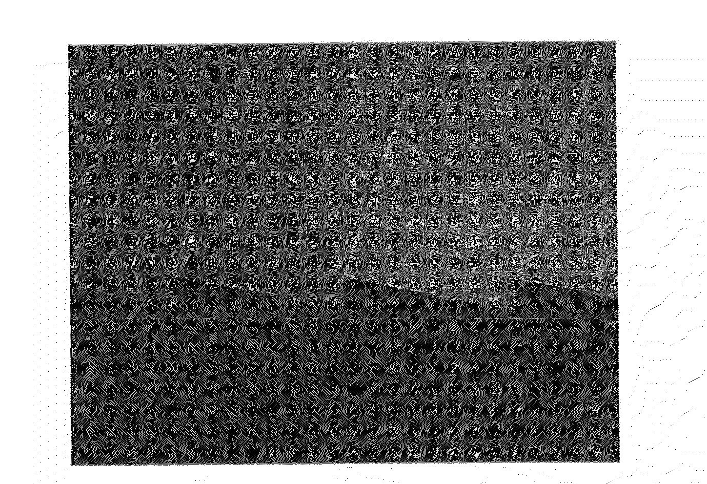
[0026]First, we now explain a situation of occurrence of burrs on a molding die when cutting grooves corresponding to the profile of a diffraction optical element with reference to FIGS. 1 to 5. In an example shown in FIGS. 1 to 5, it is noted that a die base (base material) made from appropriate steel for molding dies is adopted as a material for the molding die and that an electroless nickel plating is applied on the die base.

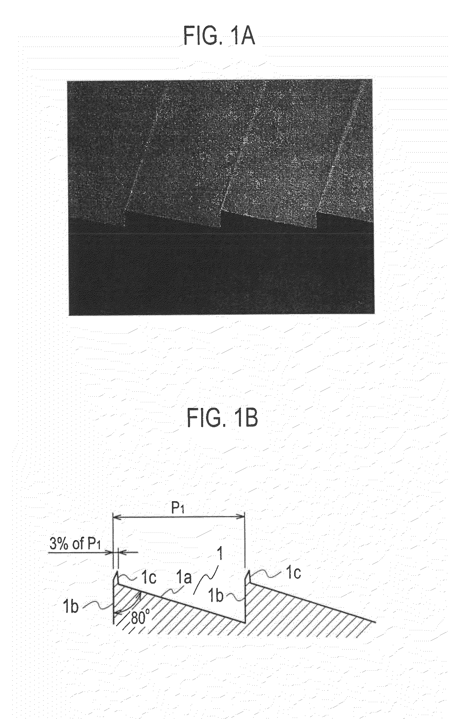
[0027]In the figures, FIG. 1A is an image view showing a die surface including grooves each having a point angle of 80 degrees, while FIG. 1B is a schematic sectional view of the die surface of FIG. 1A.

[0028]In this example shown in FIGS. 1A and 1B, a groove 1 is defined by a slanted surface 1a and a side surface 1b. These surfaces 1a, 1b are provided by using a cutting tool having a point angle of 80 degrees. A burr 1c is produced at a point portion of...


PUM


Abstract

A diffraction optical element is provided to reduce harmful lights and also suppress deterioration in the optical characteristics of the element. The diffraction optical element 22 is formed with a plurality of diffraction gratings 17′, 18′, 19′ and 20′. From these diffraction gratings, there are selected the diffraction gratings 18′, 19′ and 20′ whose groove apex angles are less than a predetermined angle. The diffraction gratings 18′, 19′ and 20′ has chamfer surfaces 18c′, 19c′ and 20c′ formed on the lower side of respective slanted surfaces 18a′, 19a′ and 20a′. The chamfer surfaces 18c′, 19c′ and 20c′ are slanted to the slanted surfaces 18a′, 19a′ and 20a′, respectively.

Description

BACKGROUND OF THE INVENTION[0001]1. Field of the Invention[0002]The present invention relates to a diffraction optical element, a molding die for the diffraction optical element and a manufacturing method of the molding die.[0003]2. Description of the Related Art[0004]Recently, with enhanced requirement for high performance and miniaturization in optical systems, a diffraction optical element has been getting people's attention. More particularly, a diffraction optical element whose diffraction gratings have a blazed profile (i.e. saw-tooth appearance) in section is frequently utilized in an optical system of an optical equipment since such a diffraction optical element is low in profile and high in diffraction efficiency.[0005]Japanese Patent Publication Laid-open No. 2002-189114 discloses a method of manufacturing such a diffraction optical element. In accordance with the disclosed manufacturing method, the diffraction optical element is produced by using plastic material and a mo...

Claims


Application Information

Patent Timeline
IPC IPC(8): G11B7/00
CPCG02B5/1847G02B27/0018G02B5/1866
Inventor IDE, HIDEKIUEKITA, MASAHIROKOIKE, EIJIRO
Owner KK TOSHIBA
Why Eureka
Try Eureka