Method of Acoustic Wave Generation

a technology of acoustic wave and amplification, applied in the direction of sonic/ultrasonic/infrasonic transmission, sonic/ultrasonic/infrasonic circuit arrangement, electrical apparatus, etc., can solve the problem of low air velocity achieved in these devices, inapplicability to commercial or industrial applications, and insufficient volume level of triode configuration for most uses, etc. problem, to achieve the effect of maximum acceptable distortion of an audio outpu

Inactive Publication Date: 2009-01-22
KRONOS ADVANCED TECH
View PDF99 Cites 16 Cited by
  • Summary
  • Abstract
  • Description
  • Claims
  • Application Information

AI Technical Summary

Benefits of technology

[0098]According to another aspect of the invention, a step of rapidly discharging electrical power stored in an external capacitance of the EFA array may be provided.
[0099]According to another aspect of the invention, a further step may include maintaining a difference between a voltage level of (i) the low-frequency voltage and (ii) a corona onset voltage of the EFA array close to a voltage level of the high-frequency voltage during each of a plurality of time periods whereby a maximum acceptable distortion of an audio output is not exceeded.

Problems solved by technology

Air velocity achieved in these devices is very low and is not practical for commercial or industrial applications.
Unfortunately, the volume level produced by the triode configuration is insufficient for most uses.

Method used


Image

  • Method of Acoustic Wave Generation
  • Method of Acoustic Wave Generation
  • Method of Acoustic Wave Generation

Examples


Embodiment Construction

[0124]For ease of presentation, the following description includes various captions and headings for purposes of reference. All such captions, headings, and division of material are not to be construed as limiting of the invention, the embodiments described therein, or otherwise. Likewise, the titles and / or descriptions of each section or division are for purposes of ease of reference and are not considered to be substantive limitations.

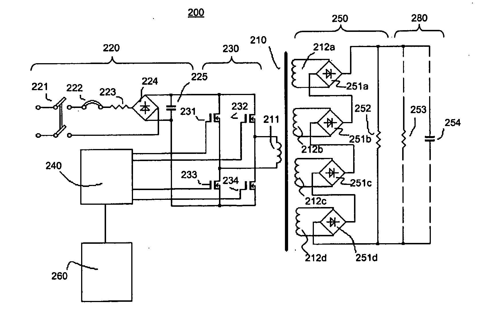
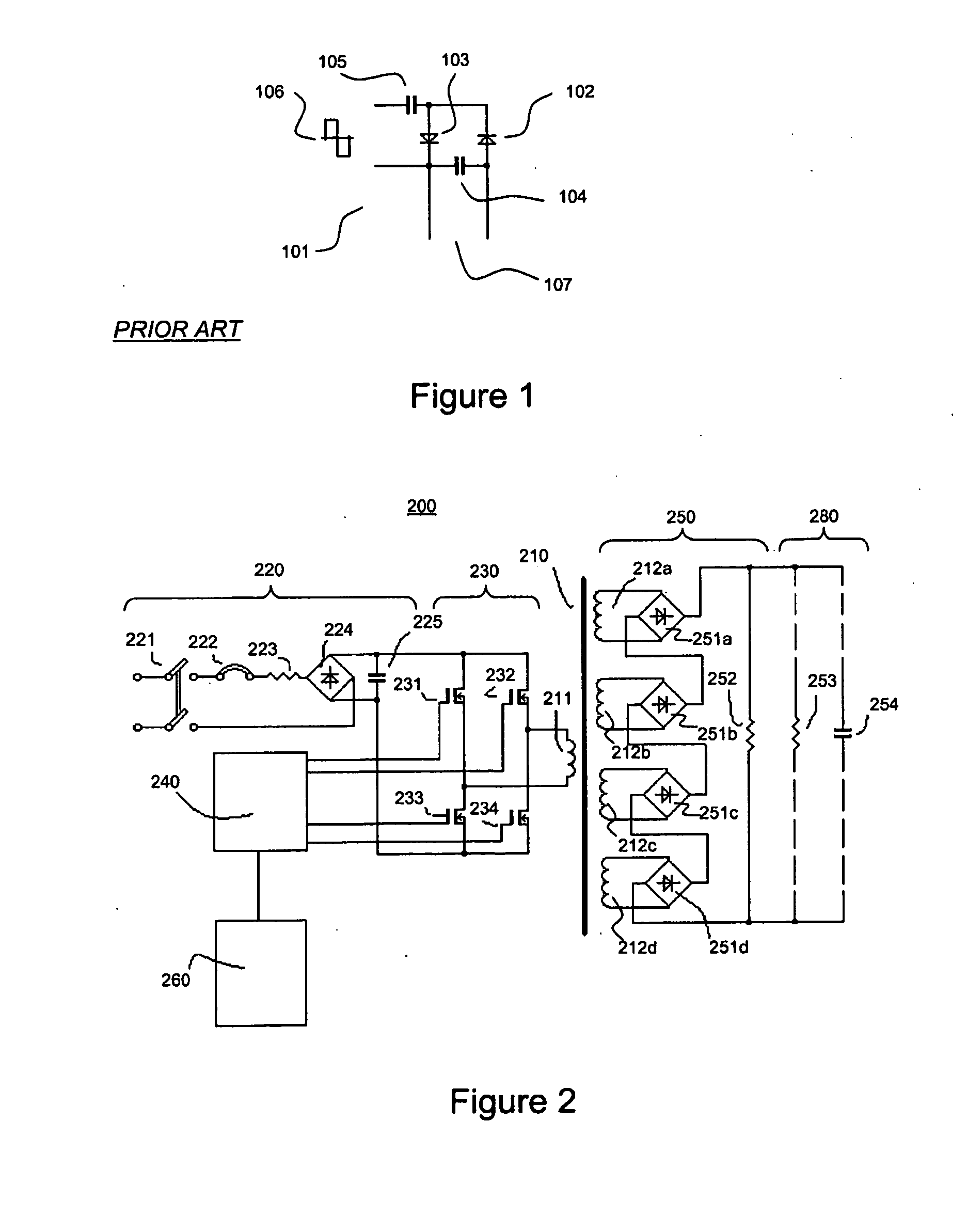
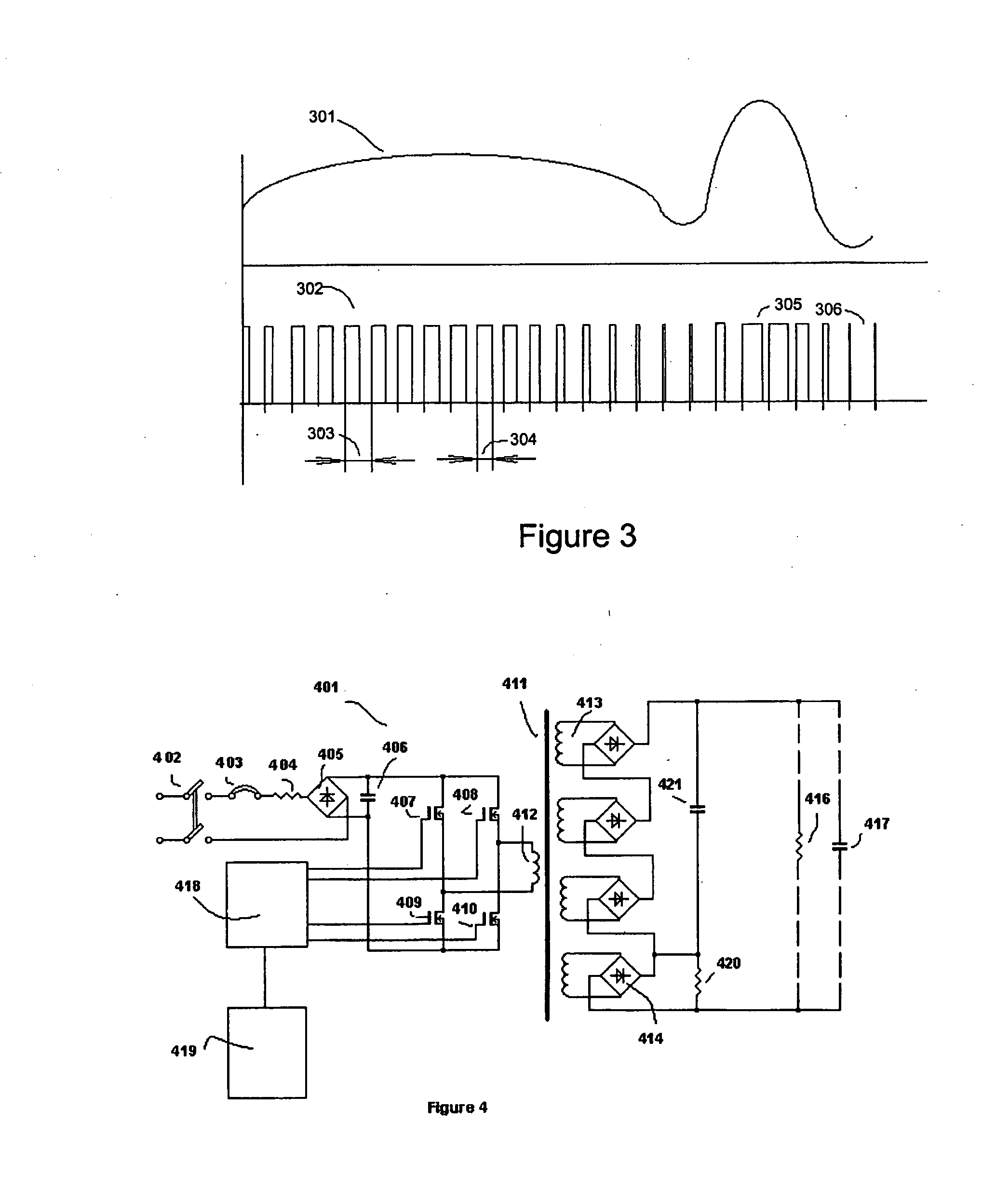
[0125]The invention is broadly directed to a sound transducer device for converting an audio signal into vibratory modulation of a fluid. For example, where the fluid is air, the device may function as a loudspeaker to generate audible acoustic or sound waves. The device may include a HVPS and an electrostatic fluid accelerator (EFA). The HVPS may include (i) a control circuit responsive to the audio signal; (ii) a power input stage responsive to the control circuit for selectively supplying input power; and (iii) a power converter stage configured t...


PUM


Abstract

A method of converting an audio signal into vibratory modulation of a fluid includes converting a series of pulses representative of the audio signal into a plurality of signals having an intermediate peak-to-peak voltage; summing said signals having said intermediate voltage to provide a driver signal having a high peak-to-peak voltage; supplying said driver signal to an electrostatic fluid accelerator; and generating a corona discharge inducing said vibratory modulation of said fluid.

Description

RELATED APPLICATIONS[0001]The present application claims the benefit of the earlier filing date of U.S. Provisional Patent Application No. 60 / 794,510 filed Apr. 25, 2006 in accordance with 35 U.S.C. § 119(e) and is related to the prior patents and patent applications of Igor Krichtafovitch et al. including, but not limited to, the following:U.S. Pat. No. 6,504,308 entitled Electrostatic Fluid Accelerator;U.S. Pat. No. 6,664,741, entitled Method Of And Apparatus For Electrostatic Fluid Acceleration Control Of A Fluid Flow;U.S. Pat. No. 6,727,657 entitled Electrostatic Fluid Accelerator For And A Method Of Controlling Fluid Flow;U.S. Pat. No. 6,888,314 entitled Electrostatic Fluid Accelerator;U.S. Pat. No. 6,919,698 entitled; Electrostatic Fluid Accelerator For And Method Of Controlling A Fluid Flow;U.S. Pat. No. 6,937,455 entitled Spark Management Method And Device;U.S. Pat. No. 6,963,479 entitled Method Of And Apparatus For Electrostatic Fluid Acceleration Control Of A Fluid Flow;U....

Claims


Application Information

Patent Timeline
Patent Type & Authority Applications(United States)
IPC IPC(8): H04B11/00
CPCH04R5/04
Inventor KRICHTAFOVITCH, IGOR A.JACOB, OHARAH L.KOROLYOV, VLADISLAV A.JEWELL-LARSEN, NELS E.KARPOV, SERGEY
Owner KRONOS ADVANCED TECH
Why Eureka
Try Eureka