Axial diffuser for a centrifugal compressor

a centrifugal compressor and axial diffuser technology, which is applied in the direction of machines/engines, stators, liquid fuel engines, etc., can solve the problems of preventing the effective efficiency of centrifugal compressor to be increased to the desired level, vortices affecting and reducing the cross sectional area of axial diffusers, so as to improve the efficiency of centrifugal compressors and reduce the pressure gradient in each cross section

Active Publication Date: 2009-01-22
HONDA MOTOR CO LTD
View PDF5 Cites 6 Cited by
  • Summary
  • Abstract
  • Description
  • Claims
  • Application Information

AI Technical Summary

Benefits of technology

[0012]Thereby, the fluid velocity can be made uniform across the cross section of each diffuser passage, from the positive pressure side to the negative pressure side, and from the upstream end to the downstream end thereof, and can be made highly uniform across the cross section of the axial diffuser passage at the downstream end thereof. This contributes to the improvement in the efficiency of the centrifugal compressor. Preferably, the cross section of each axial diffuser passage is substantially elliptic or track shaped, and each axial diffuser passage is defined by an individual tube member. Typically, the upstream end of each axial diffuser passage extends tangentially from a peripheral part of the impeller.
[0013]According to a preferred embodiment of the present invention, the cross section of each axial diffuser passage has a minor axis and a major axis, and the minor axis extends substantially perpendicularly to a direction directed from a center of the cross section to the central axial line of the impeller. Alternatively, the minor axis and major axis may extend substantially perpendicularly to each other while the minor axis is directed toward the central axial line of the impeller. Thereby, the negative pressure side and positive pressure side of each cross section of the axial diffuser passage can be kept at a same distance from the central axial line of the centrifugal compressor.
[0014]Thus, the pressure gradient in each cross section of the axial diffuser passage owing to a centrifugal force can be minimized, and the unevenness in the flow of the compressed air in the axial diffuser passage can be minimized. In particular, the accumulation of uneven, low velocity air flow on the negative pressure side can be avoided. Also, the reduction in the unevenness of pressure which is otherwise created in each cross section owing to a centrifugal force contributes to the prevention of flow separation on the negative pressure side. The uniform distribution of fluid flow velocity at the outlet end of each axial diffuser passage, combined with the prevention of flow separation, increases the static pressure recovery ratio Cp, and improves the effective efficiency of the centrifugal compressor.

Problems solved by technology

As a result, a part of the kinetic energy of the fluid flow is dissipated as heat, and the vortices diminish the effective cross sectional area of the fluid passage by blocking the fluid flow.
Therefore, in a conventional axial diffuser, the static pressure recovery ratio Cp=(static pressure at diffuser outlet−static pressure at diffuser inlet) / (total pressure at diffuser inlet−static pressure at diffuser inlet) is not so high as desired, and this prevented the effective efficiency of a centrifugal compressor to be increased to a desired level.

Method used


Image

  • Axial diffuser for a centrifugal compressor
  • Axial diffuser for a centrifugal compressor
  • Axial diffuser for a centrifugal compressor

Examples


Embodiment Construction

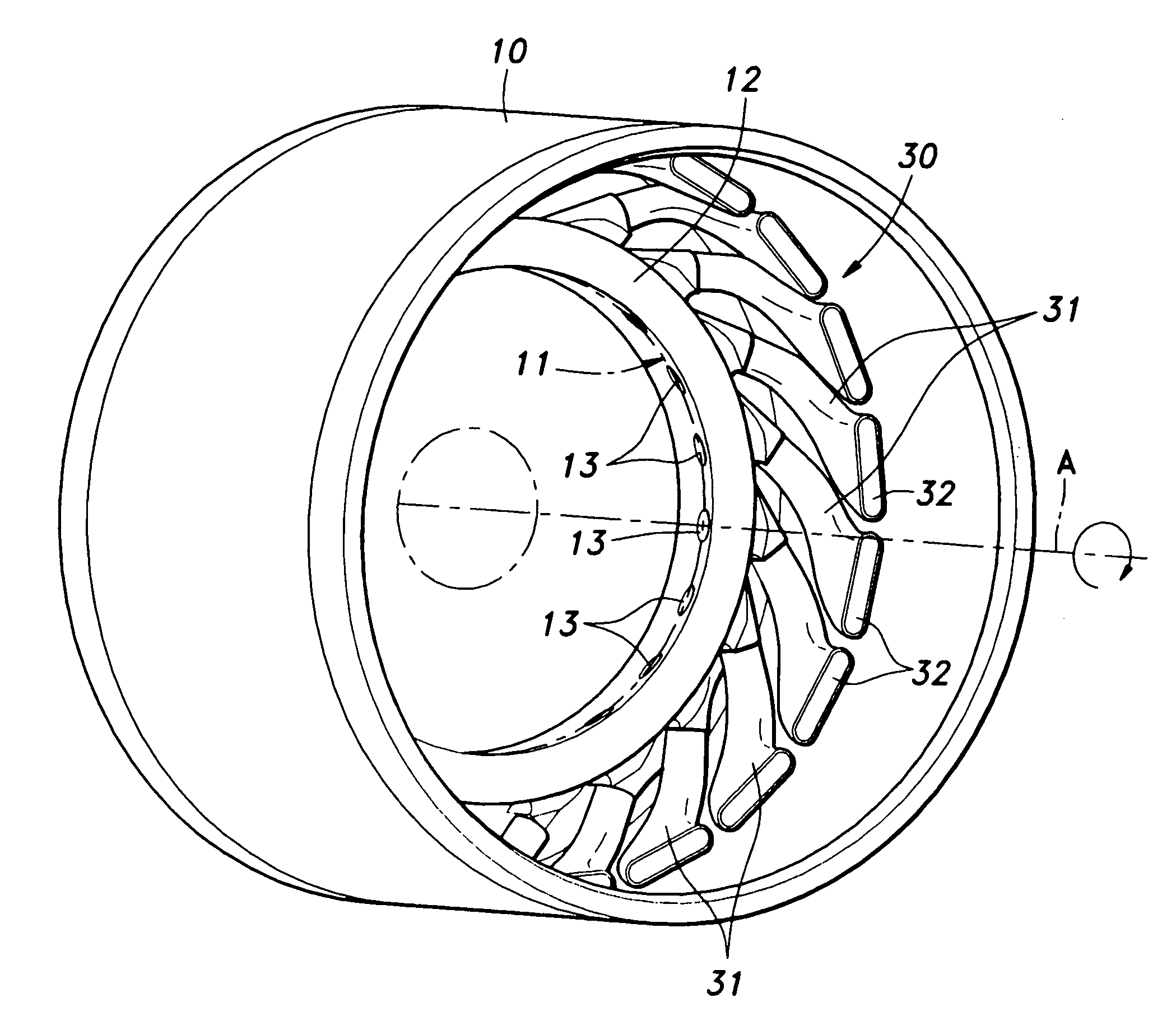
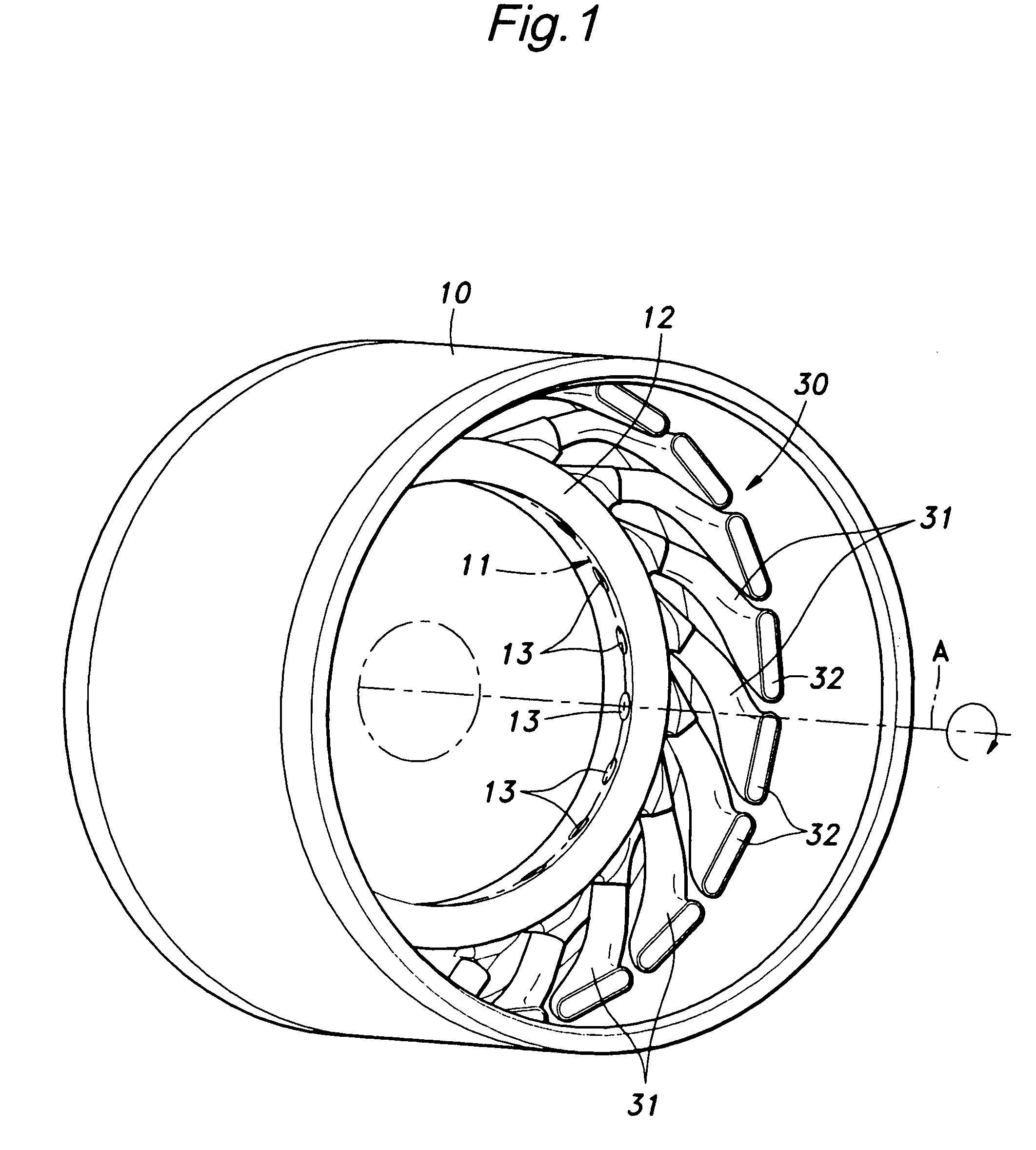
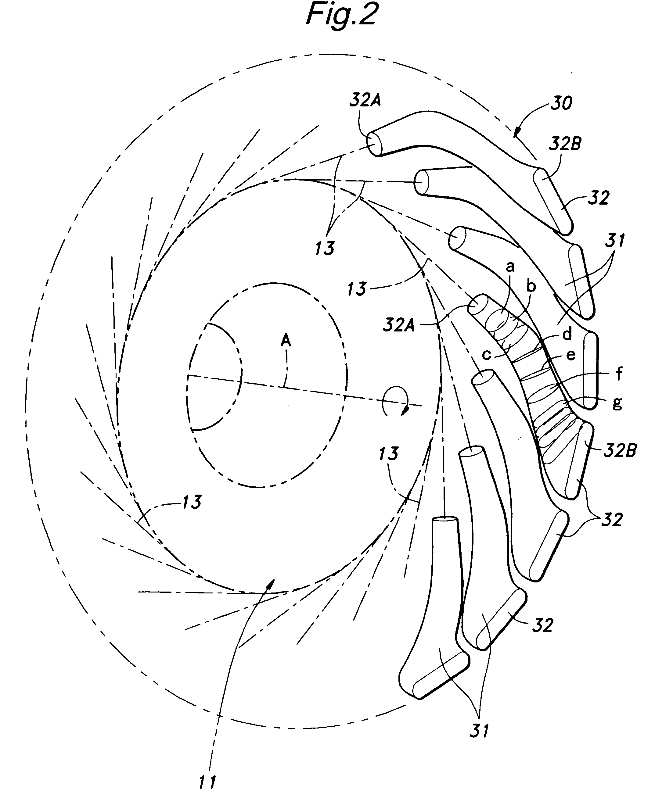
[0026]Inside a cylindrical outer housing 10 of a centrifugal compressor, an impeller 11 is supported so as to be rotatable around a central axial line A thereof. In FIGS. 1 to 3, the centrifugal compressor is viewed from the rear side thereof (downstream side with respect to the compressed air), and the impeller 10 rotates in clockwise direction, and only the outer periphery of the impeller 11 is indicated by a dotted line in FIG. 1.

[0027]An annular radial diffuser member 12 is fixedly attached to the outer housing 10 so as to concentrically surround the impeller 11, and is formed with a plurality of radial diffuser passages 13 arranged at a regular circumferential interval. Each radial diffuser passage 13 extends linearly in a tangential direction, and has a cross sectional area that progressively increases toward the downstream end thereof.

[0028]Each of the radial diffuser passages 13 formed in the radial diffuser member 12 reduces the velocity of the radial flow of the fluid (com...


PUM


Abstract

The effective efficiency of a centrifugal compressor can be improved by achieving a uniform distribution of fluid velocity across the outlet end of a fluid passage of an axial diffuser for the centrifugal compressor and a high static pressure recovery ratio Cp in the axial diffuser passage. The cross section of each axial diffuser passage is configured such that a relatively high velocity fluid flow in an upstream part of the diffuser passage is directed toward a negative pressure side of a cross section thereof. It can be accomplished by directing a minor axis of a cross section of the diffuser passage substantially perpendicularly to a direction directed from a center of the cross section of the diffuser passage to the central axial line of an impeller or directing the minor axis toward the central axial line of the impeller.

Description

TECHNICAL FIELD[0001]The present invention relates to an axial diffuser for a centrifugal compressor, and in particular to an axial diffuser for a centrifugal compressor of a gas turbine engine or a jet engine.BACKGROUND OF THE INVENTION[0002]The centrifugal compressor used in a gas turbine engine or a jet engine typically includes an axial diffuser. In an axial diffuser, a plurality of axial diffuser passages are provided around the impeller at a regular circumferential interval, and as the radial flow of the fluid (compressed air) expelled from the impeller flows through each of the axial diffuser passages, the fluid flow is directed into an axial flow which is substantially in parallel with the central axial line of the impeller, and the kinetic energy of the fluid flow is converted into pressure energy. See U.S. Pat. No. 6,280,139, for instance.[0003]Also is known the radial diffuser which is used in a centrifugal compressor to convert the kinetic energy of the fluid expelled fr...

Claims


Application Information

Patent Timeline
Patent Type & Authority Applications(United States)
IPC IPC(8): F04D29/44
CPCF04D29/441
Inventor HONDA, SHUICHIOANA, MINEYASUNAKATA, HIDEHIKOKUNO, NAOKI
Owner HONDA MOTOR CO LTD
Why Eureka
Try Eureka