
Downhole shock absorber for torsional and axial loads

a shock absorber and downhole technology, applied in the direction of drilling rods, drilling pipes, drilling casings, etc., can solve the problems of reducing the useful life affecting the stability of the drill bit,

Inactive Publication Date: 2009-01-22
DIAMONDBACK - QUANTUM DRILLING MOTORS
View PDF11 Cites 73 Cited by
  • Summary
  • Abstract
  • Description
  • Claims
  • Application Information

AI Technical Summary

Benefits of technology

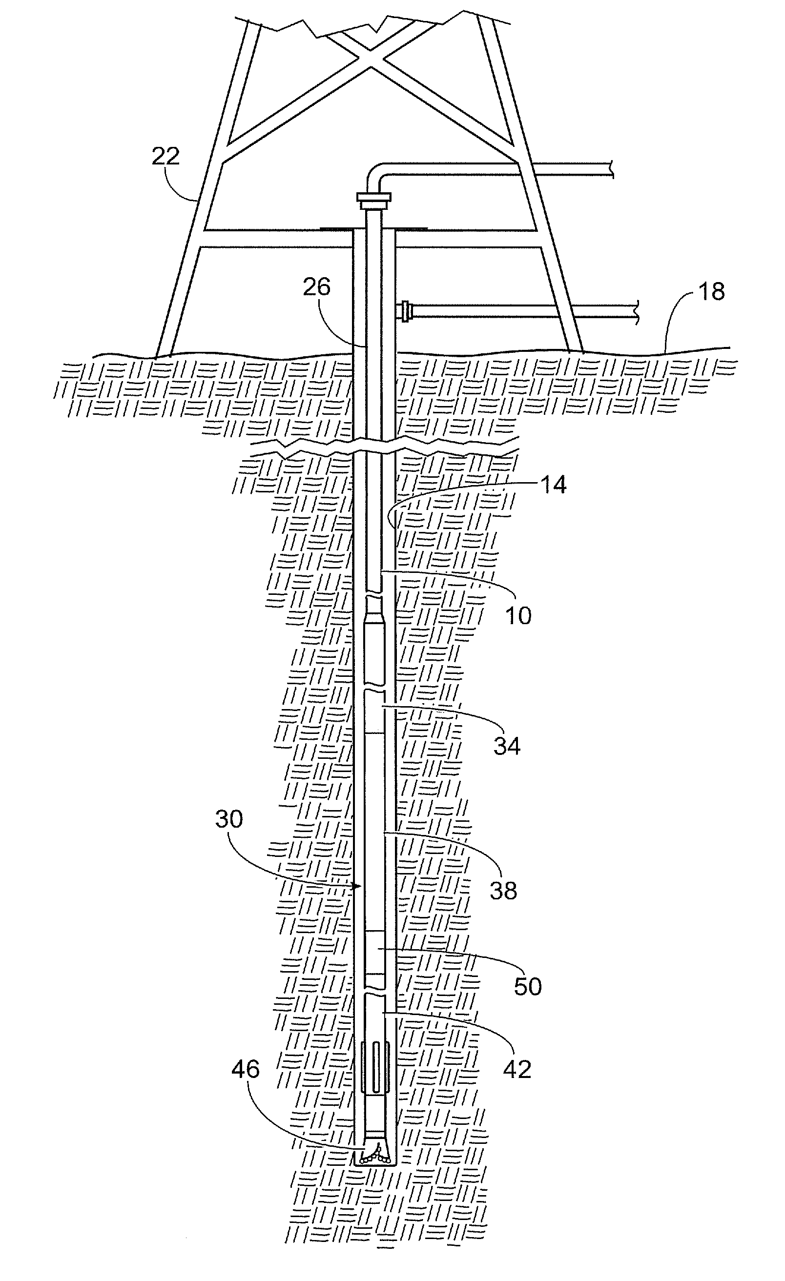
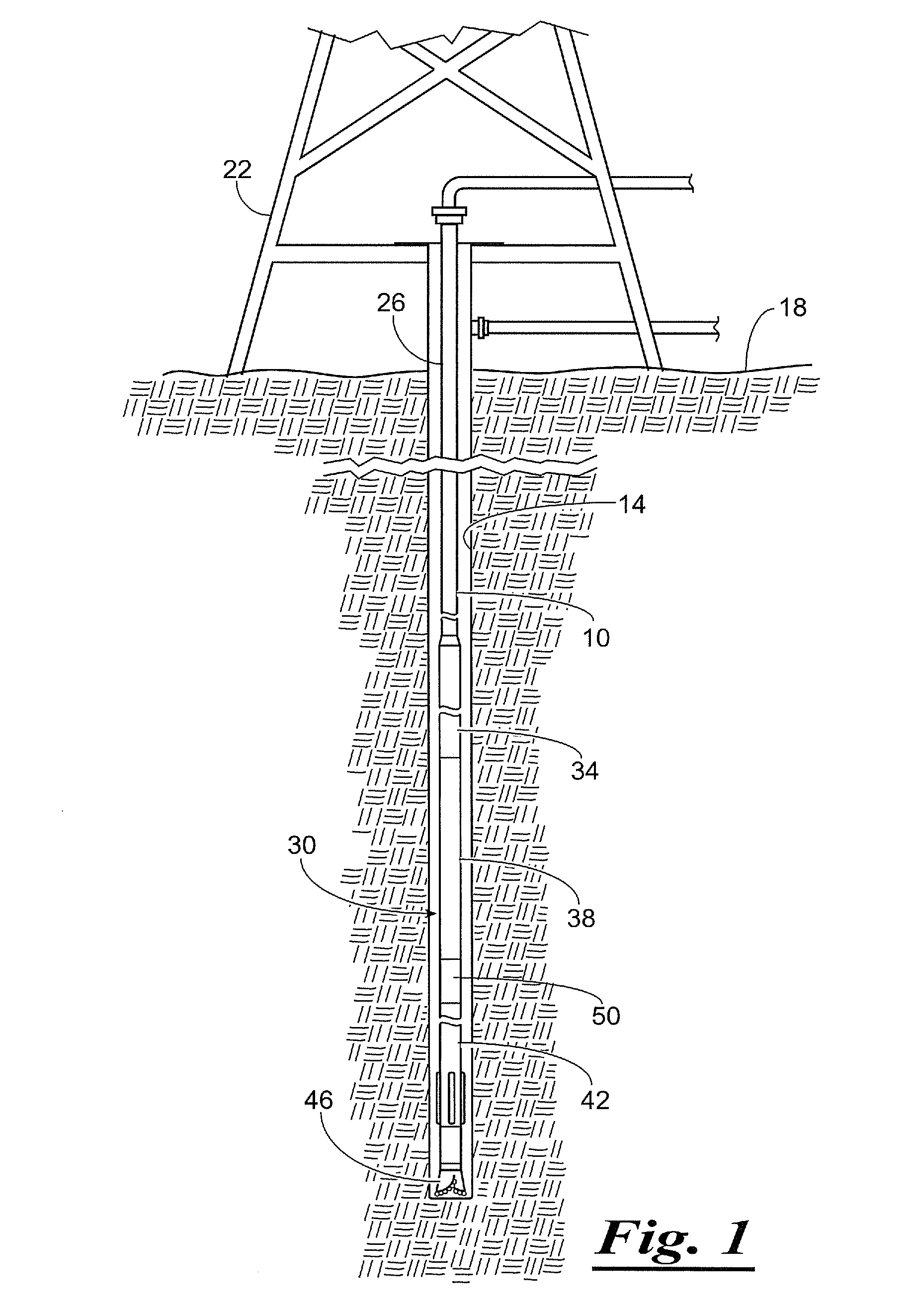
[0017]The drill bit 46 is rotated by the mud motor 42 which responds to the flow of drilling fluid, or mud, which is pumped from a mud tank (not shown) through a central passageway or mud channel through the drill pipe 26, drill collars 34, the instrumented drill pipe 38, the shock-absorber subassembly 50, and then to the mud motor 42. The pumped drilling fluid jets out of the drill bit 46 and flows back to the surface through an annulus formed between the drill string 10 and the wellbore 14. The drilling fluid carries debris away from the drill bit 46 as the drilling fluid flows back to the surface. The drill collars 34 provide a means to provide weight on the drill bit 46 while maintaining the drill pipe 26 in tension, enabling the drill bit 46 to crush and cut the formations as the mud motor 42 rotates the drill bit 46.
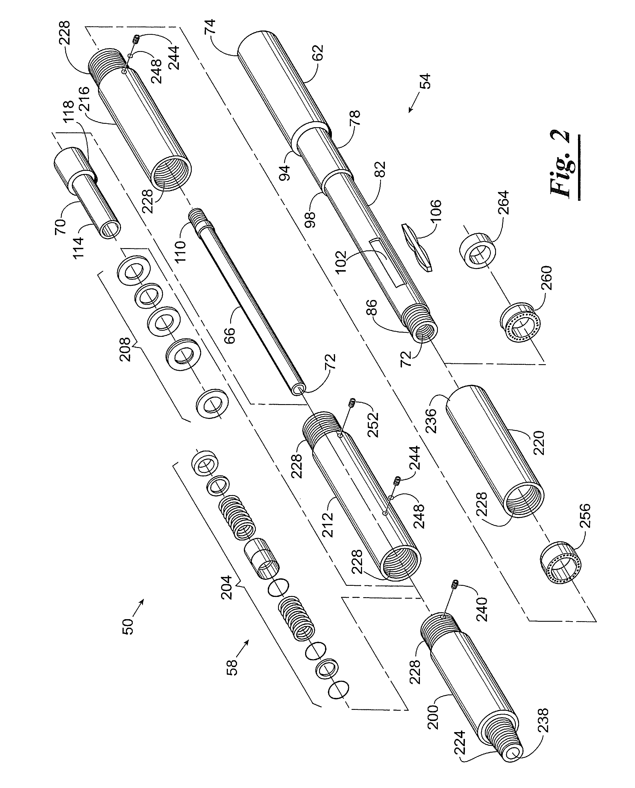
[0019]Similarly, to help ensure consistent and efficient drilling, it is desirable to have one or more shock-absorber assemblies 50 disposed above the drill bit 46 in the drill string 10. The shock-absorber subassembly 50 preferably reduces the transfer of torsional and / or axial shocks and vibrations between the drill bit and the drill string 10. The present invention is directed to several embodiments of an improved version of a shock-absorber subassembly 50.

Problems solved by technology

In drilling through such formations, the drill bit may generate significant vibrations, shocks, and impact loads.
If transmitted to the drill string, the vibrations, shocks, and impact loads will eventually cause metal fatigue which could result in cracking and ultimate failure of joints between drill string segments, as well as entire drill string components.
The direct transfer of these loads from the drill bit to the drill string reduces the useful life of the drill bit.
Additionally, the efficiency may be reduced because the shocks and impact loads may cause the drill bit to “jump” or lose contact with the surface being drilled.
Vibrations, shocks, and impact loads may also have an adverse affect on sensors and electronics located within the drill string.
While such sensors provide highly useful information about the down-hole drilling environment, vibration due to the drilling process can damage the sensors.
An axial load is applied to the drill bit during drilling into underlying formations, and this produces vibrations in the overlying drill string, and vibration can occur due to drill string rotation in a deviated or directional well bore.
While most of these sensors are sufficiently robust to address the vibrations of normal drilling conditions, extended vibrations, and especially heavy shocks or impact loads may have adverse affects on the data measured by the sensors, and may eventually lead to sensor damage and failure.
Additionally, the interdependence of the geometry may reduce the effectiveness of the shock absorber with respect to both axial and torsional loads.

Method used


Image

  • Downhole shock absorber for torsional and axial loads
  • Downhole shock absorber for torsional and axial loads
  • Downhole shock absorber for torsional and axial loads

Examples


Embodiment Construction

[0016]Referring to the drawings, and more particularly to FIG. 1, a subsurface drilling assembly is depicted as an example of one context for the use of the present invention. The depiction is purely illustrative and exemplary, and is not intended to be limiting in any way. Specifically, a drill string 10 is shown suspended in a wellbore 14 and supported at the surface 18 by a drilling rig 22. The drill string 10 includes multiple joints of drill pipe 26 coupled to a downhole tool assembly 30. The downhole tool assembly 30 includes multiple drill collars 34, an instrumented drill pipe 38, a mud motor 42, and a drill bit 46. The drill string 10 also preferably comprises a shock-absorber subassembly 50. The shock-absorber subassembly is most preferably disposed immediately above the mud motor 42, but may also be disposed between the mud motor 42 and the drill bit 46, or otherwise disposed further up the drill string 10 from the mud motor 42.

[0017]The drill bit 46 is rotated by the mud...


PUM


Abstract

A shock-absorber subassembly for a subsurface drilling assembly is disclosed. The shock-absorber subassembly comprises a mandrel, a body assembly, and at least one torsional spring assembly. The mandrel has a bore extending therethrough and has one end connectable to a portion of the subsurface drilling assembly. The body assembly has a bore extending therethrough and one end connectable to another portion of the subsurface drilling assembly. The body assembly is coupled to the mandrel to establish fluid communication between the bore of the mandrel and the bore of the body assembly and to permit planar rotational movement of the mandrel relative to the body assembly. The at least one torsional spring assembly engages the mandrel and the body assembly to absorb torsional shocks and vibrations between the mandrel and the body assembly and to limit the degree of planar rotation between the mandrel and the body assembly. In a second embodiment, the body assembly is coupled to the mandrel to permit axial movement as well as planar rotational movement. In this second embodiment, the shock-absorber subassembly further comprises at least one axial spring assembly engaging the mandrel and the body assembly to absorb axial shocks and vibrations between the mandrel and the body assembly.

Description

BACKGROUND OF THE INVENTION[0001]1. Field of the Invention[0002]The present invention relates generally to a vibration-dampening and shock-absorbing device, and more particularly, but not by way of limitation, to a shock-absorber subassembly adapted to engage a subsurface drilling assembly above the drill bit, the shock-absorber subassembly provided with at least one resilient shock absorber for absorbing torsional vibrations, shocks, and impact loads to prevent and reduce wear on drilling components.[0003]2. Brief Description of Related Art[0004]During the drilling of an oil or gas well, a drill string is rotated from the surface causing a drill bit to cut and crush rock formations with the weight of drill collars assisting in driving the drill bit downward into contact with the underlying rock. Drill collars also act as conduits for the drilling fluids or “mud” used to lubricate the drill bit and carry cuttings back to the surface. Mud motors and turbines are sometimes employed do...

Claims


Application Information

Patent Timeline
IPC IPC(8): E21B17/20E21B7/00
CPCE21B17/07
Inventor KOGER, WILLIAM C.
Owner DIAMONDBACK - QUANTUM DRILLING MOTORS
Learn More