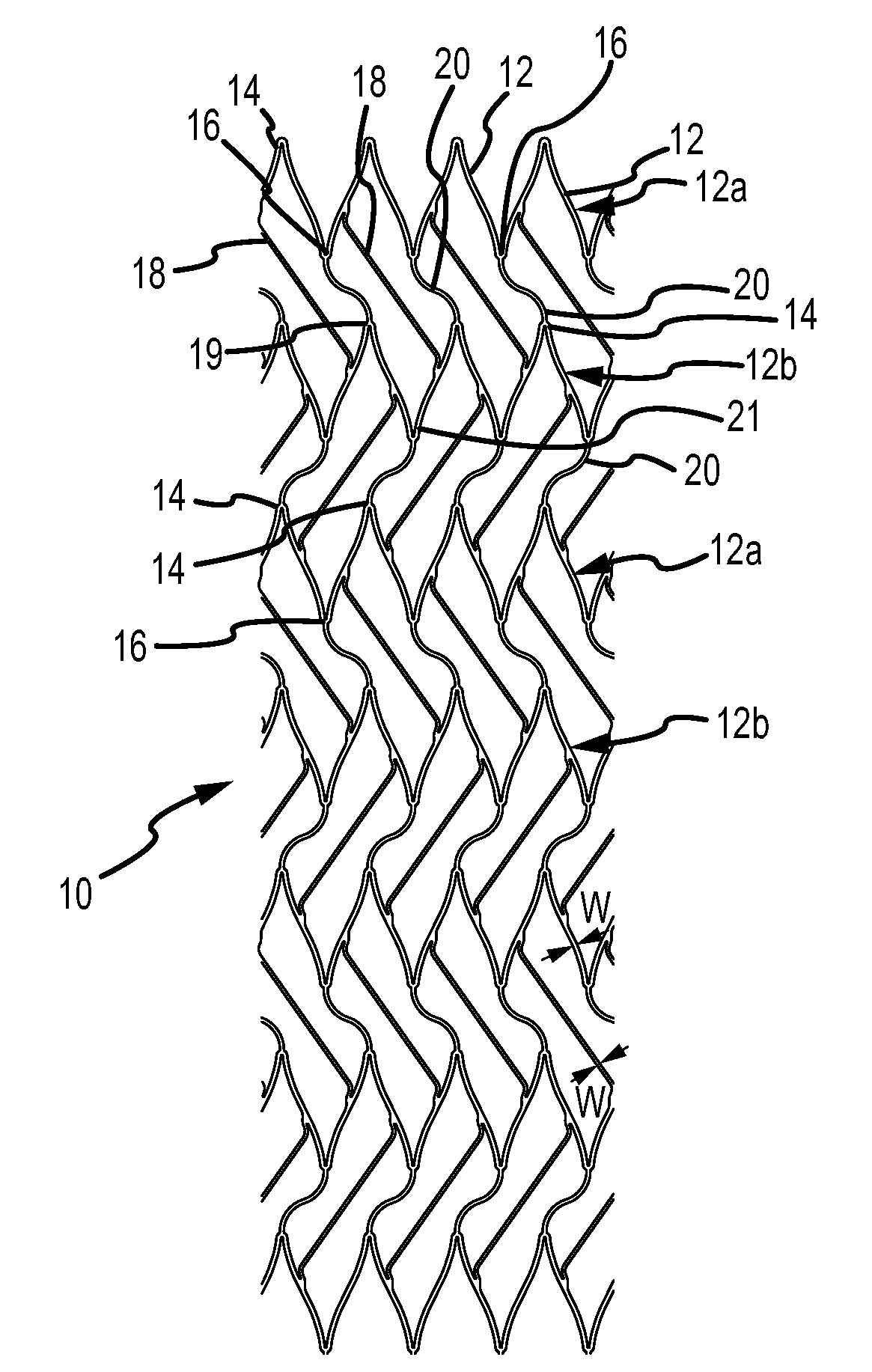
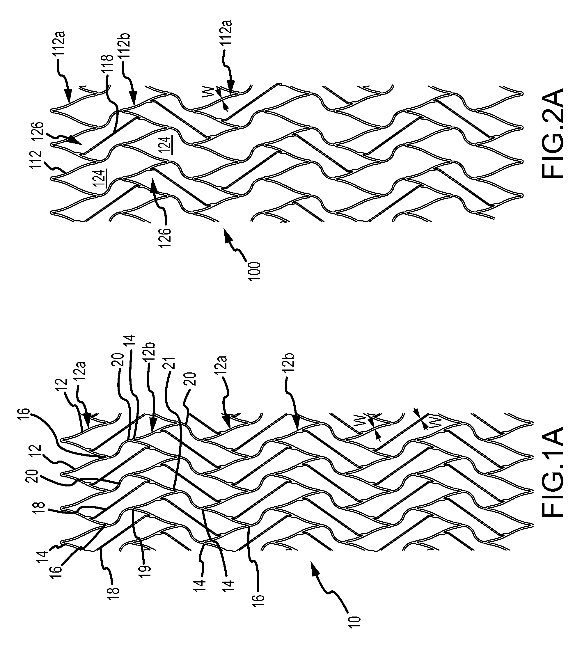
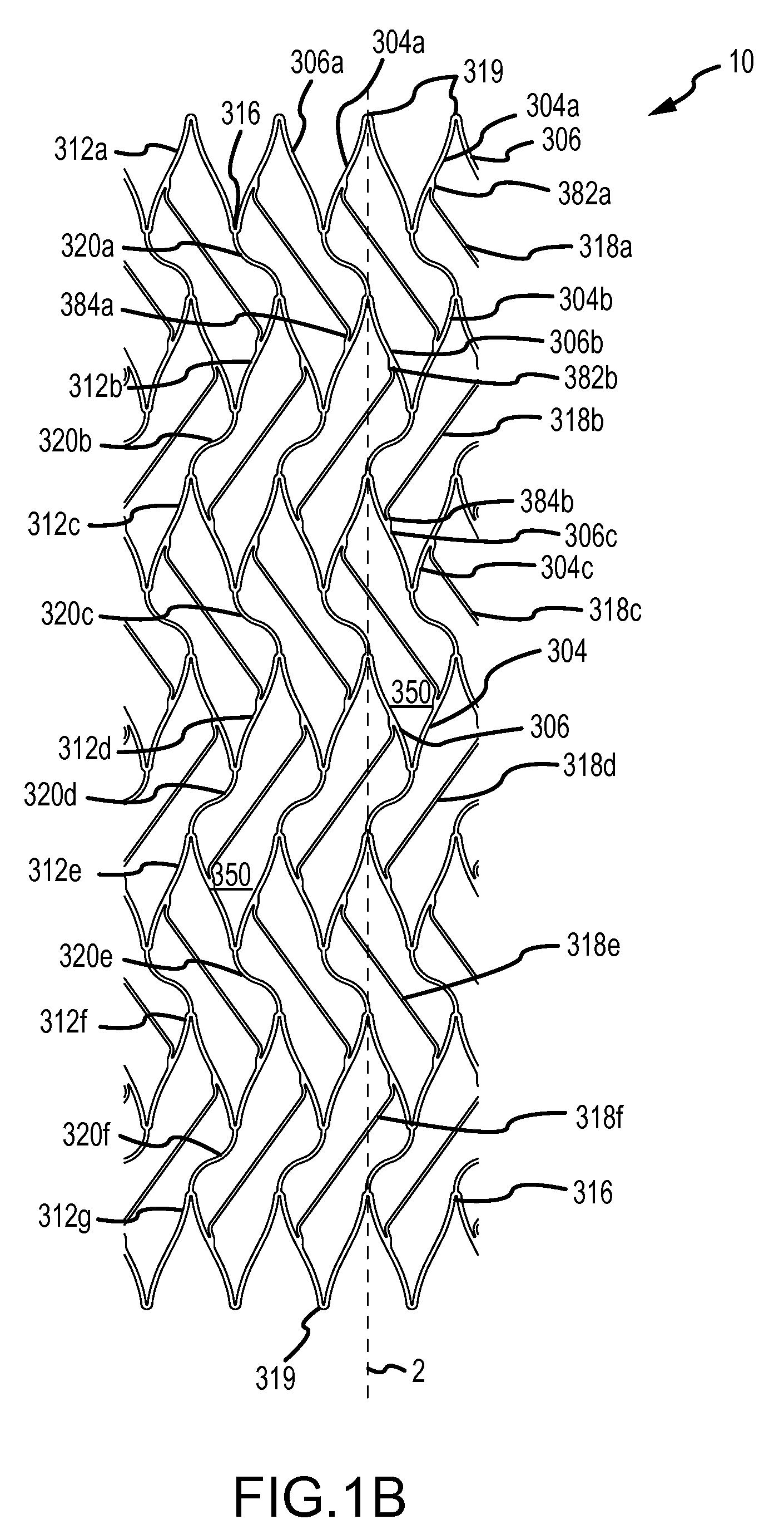
[0010]A stent that is compressible to small diameters is described. In accordance with one embodiment a stent is provided comprising: at least first, second and third spaced-apart, radially expandable rings that are substantially aligned along a longitudinal axis, each ring comprising a plurality of first struts and a plurality of second struts, the first and second struts being connected to form an undulating pattern that has peak portions and valley portions, first curved connectors joining one or more of the valley portions of the first ring to one or more of the peak portions of the second ring, the valley portions and peak portions being circumferentially offset from one another, second curved connectors joining one or more of the valley portions of the second ring to one or more of the peak portions of the third ring, the valley portions and peak portions being circumferentially offset from one another, a first intermediate strut extending between a first strut of the first ring to a first strut of the second ring without intersecting any of the other first and second struts and first and second curved connectors and; a second intermediate strut extending between a second strut of the second ring to a second strut of the third ring without intersecting any of the other first and second struts and first and second curved connectors, the first and second intermediate struts being connected to locations on the first and second struts, respectively, such that no portions of the first and second intermediate struts overlap either in a circumferential direction around the stent or in an axial direction along the stent, in use, the stent movable from a first delivery position to a second placement position, in the first delivery position the stent being in an unexpanded position and having a first diameter and in the second position the stent being in a radially expanded position and having a second diameter greater than the first diameter for placement at a treatment site of a patient.
[0011]In another embodiment a stent is provided comprising: at least first, second, third and fourth spaced-apart, radially expandable rings that are substantially aligned along a longitudinal axis, each ring comprising a plurality of first struts and a plurality of second struts, the first and second struts being connected to form an undulating pattern that has peak portions and valley portions, first curved connectors joining one or more of the valley portions of the first ring to one or more of the peak portions of the second ring, the valley portions and peak portions being circumferentially offset from one another, second curved connectors joining one or more of the valley portions of the second ring to one or more of the peak portions of the third ring, the valley portions and peak portions being circumferentially offset from one another, third curved connectors joining one or more of the valley portions of the third ring to one or more of the peak portions of the fourth ring, the valley portions and peak portions being circumferentially offset from one another, a first intermediate strut extending between a first strut of the second ring to a first strut of the third ring without intersecting any of the other first and second struts and first and second curved connectors and; a second intermediate strut extending between a second strut of the third ring to a second strut of the fourth ring without intersecting any of the other first and second struts and first and second curved connectors, the first and second intermediate struts being connected to locations on the first and second struts, respectively, such that no portions of the first and second intermediate struts overlap either in a circumferential direction around the stent or in an axial direction along the stent, in use, the stent movable from a first delivery position to a second placement position, in the first delivery position the stent being in an unexpanded position and having a first diameter and in the second position the stent being in a radially expanded position and having a second diameter greater than the first diameter for placement at a treatment site of a patient.
[0012]The stents of the present invention are highly compressible and can assume compressed diameters sufficient for mounting and delivering the stents on or within small diameter delivery devices (e.g., elongate wires, catheters, etc.) while exhibiting the scaffolding, radial force, radiopacity and kink resistant properties sufficient for treatment of small diameter vessels or ducts.
