Steer-by-wire system for automobiles

a technology of steering wires and automobiles, applied in the direction of steering initiation, underwater equipment, instruments, etc., can solve the problems of complex above-described hydraulic systems, lack of smooth steering feel, steering-by-wire systems, etc., and achieve the effect of minimizing the difference in steering feel

Inactive Publication Date: 2009-01-22
HYUNDAI MOTOR CO LTD
View PDF3 Cites 58 Cited by
  • Summary
  • Abstract
  • Description
  • Claims
  • Application Information

AI Technical Summary

Benefits of technology

[0012]Accordingly, the present invention has been made keeping in mind the above problems occurring in the prior art, and provides a steer-by-wire system, in which control logic, which can more precisely control the generation of steering reaction force and restoring force, generate an appropriate damping force acting in the reverse direc...

Problems solved by technology

However, the above-described hydraulic system is complicated because it is constructed using complicated hydraulic lines, that is, because the oil reservoir, the oil pump, the gear box, and the plurality of hoses for connecting them must be provided.
Although the steer-by-wire system is expected to be the next generation power steering system due to its advantages that the construction thereof is simple because a small number of mechanical devices is used and that the fuel consumption rate is decreased, the steer-by-wire system is problematic in that, unlike an automobile (hereinafter referred to as an “actually used vehicle”) that employs the hydraulic system, it does not provide a smooth steering feel,_because a digital control method using a steering motor, rather than an analog control method, such as that of the conventional hydraulic system,...

Method used


Image

  • Steer-by-wire system for automobiles
  • Steer-by-wire system for automobiles
  • Steer-by-wire system for automobiles

Examples


Embodiment Construction

[0026]Hereinafter reference will now be made in detail to various embodiments of the present invention, examples of which are illustrated in the accompanying drawings and described below. While the invention will be described in conjunction with exemplary embodiments, it will be understood that present description is not intended to limit the invention to those exemplary embodiments. On the contrary, the invention is intended to cover not only the exemplary embodiments, but also various alternatives, modifications, equivalents and other embodiments, which may be included within the spirit and scope of the invention as defined by the appended claims.

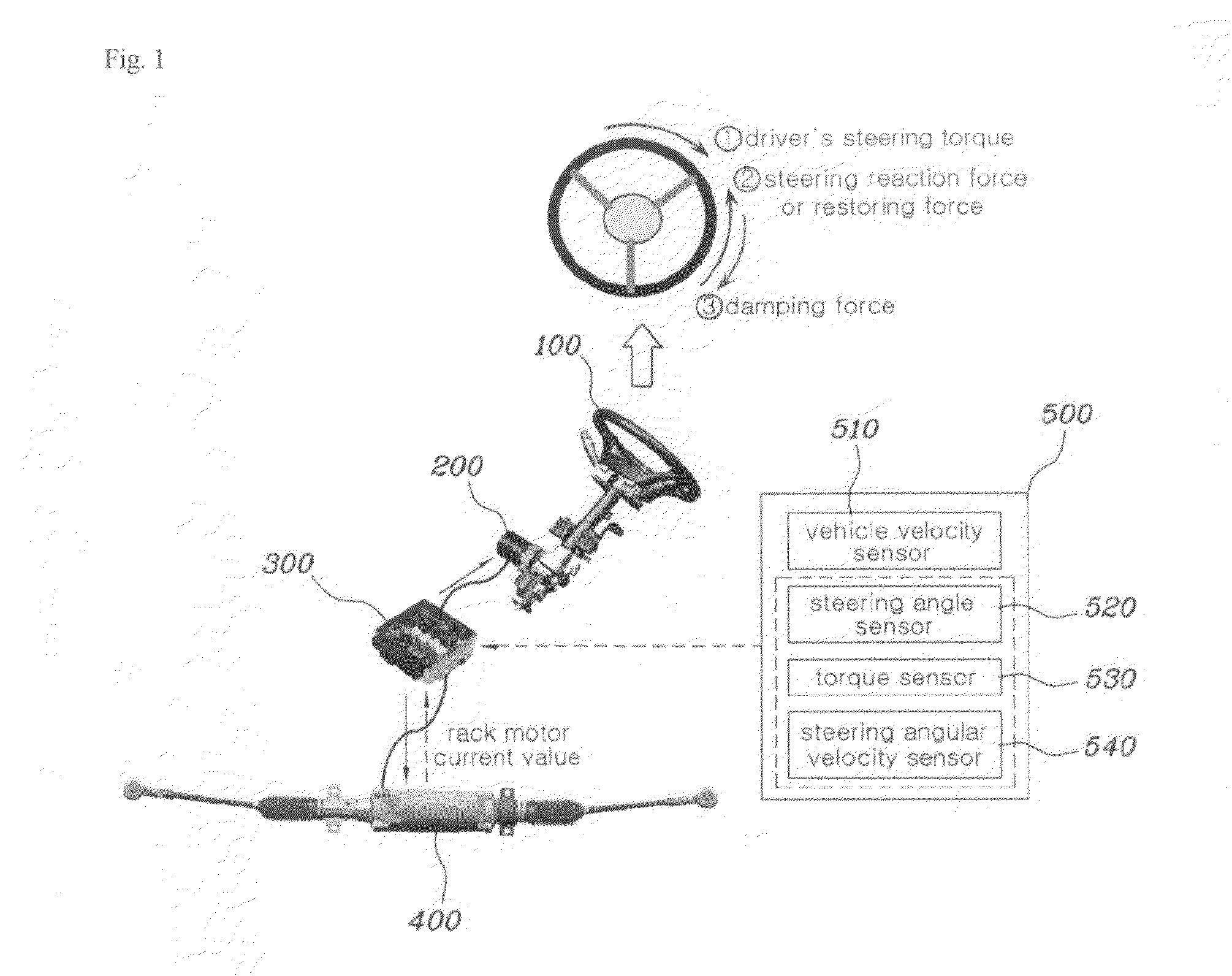
[0027]The basic construction of a steer-by-wire system for automobiles according to the present invention is described with reference to FIG. 1 below.

[0028]The steer-by-wire system is a next generation steering device, and is configured such that a steering control unit 100, which is coupled with a steering wheel, and a steering mechanism...


PUM


Abstract

Disclosed herein is a steer-by-wire system for automobiles. The steer-by-wire system includes a steering control unit and a signal input unit. The central control unit includes a reaction force generation unit, a damping force generation unit. The reaction force generation unit generates steering reaction force or restoring force, acting in the reverse direction to that of a steering torque. The damping force generation unit generates damping force, acting in the reverse direction to the steering reaction force or the restoring force (in the same direction as the steering torque). Furthermore, the central control unit generates a current control signal, which is applied to a steering feel generation motor, by combining the resulting values determined by the reaction force generation unit and the damping force generation unit a vehicle velocity signal in response to a steering angle signal, a steering torque signal and a steering angular velocity signal.

Description

CROSS-REFERENCE TO RELATED APPLICATIONS[0001]This application claims priority to Korean Application No. 10-2007-0071758, filed on Jul. 18, 2007, the disclosure of which is incorporated herein by reference.BACKGROUND OF THE INVENTION[0002]1. Field of the Invention[0003]The present invention relates generally to a steer-by-wire system for automobiles, in which control logic, which can generate damping force acting in the reverse direction to that of steering reaction force, correct a difference between the left and right frictional forces of a rack motor, and adjust a steering feel according to road conditions, is additionally provided, thus more precisely controlling steering reaction force (or restoring force), with the result that the steering feel can be improved.[0004]2. Description of the Related Art[0005]Conventionally, a hydraulic system has been chiefly used as a power steering system. Such a hydraulic power steering system is configured such that a gear box, in which a pinio...

Claims


Application Information

Patent Timeline
IPC IPC(8): B62D6/00
CPCB62D6/008B62D5/006B62D5/06B60W2710/20B60Y2400/307B60Y2400/303
Inventor HWANG, SUNG WOOK
Owner HYUNDAI MOTOR CO LTD
Why Eureka
Try Eureka