Monitoring System for Virtual Application Environments

Active Publication Date: 2009-01-22
EG INNOVATIONS PTE
View PDF18 Cites 86 Cited by
  • Summary
  • Abstract
  • Description
  • Claims
  • Application Information

AI Technical Summary

Benefits of technology

[0043]The method may also include the step of allowing an administrator to select those metrics to form the various sets of metrics to be monitored. Similarly, the method may allow the administrator to select the amount of time

Problems solved by technology

The problem with such systems is that “outside” view information alone does not provide a complete view of the operations of the data network.
Without this complete view, effective capacity planning decisions regarding the data network may not be made through ignorance of other constraining factors.
Additionally, without a complete view of the operations of the data network, accurately identifying problems with the virtual machine environment of the data network is almost impossible.
To elaborate, because each virtual machine operates as an individual process on the operating system of the physical machine, but internally oper

Method used


Image

  • Monitoring System for Virtual Application Environments
  • Monitoring System for Virtual Application Environments
  • Monitoring System for Virtual Application Environments

Examples


first embodiment

[0105]As a detailed description of how to obtain such metrics using APIs and commands has been provided in the invention, it will not be repeated here.

[0106]The values obtained for each required metric are then transmitted by the agent program 14 (step 224). In response the manager program 12 sends an identifier representative of the latest configuration for the monitoring system along with, or in place of, an acknowledgement of the reported data (step 226). If the identifier of the latest configuration reported by the manager program 12 is later than the identifier of the configuration the agent program 14 is currently operating under, the agent program 14 operates to download the new configuration by repeating the above methodology from step 212. Alternatively, if the timestamps of the two configurations remain identical, the agent program 14 passes processing to step 230 (step 228).

[0107]At step 230, the agent program 14 assesses whether one or more of the metrics to be monitored...

third embodiment

[0112]In accordance with the invention, where like numerals reference like parts, there is a monitoring system 300 for virtual application environments. The monitoring system 300 comprises a manager program 302 and a single agent program 304. The manager program 302 and the agent program 304 each take the form of object code able to be executed on a stand-alone system 310.

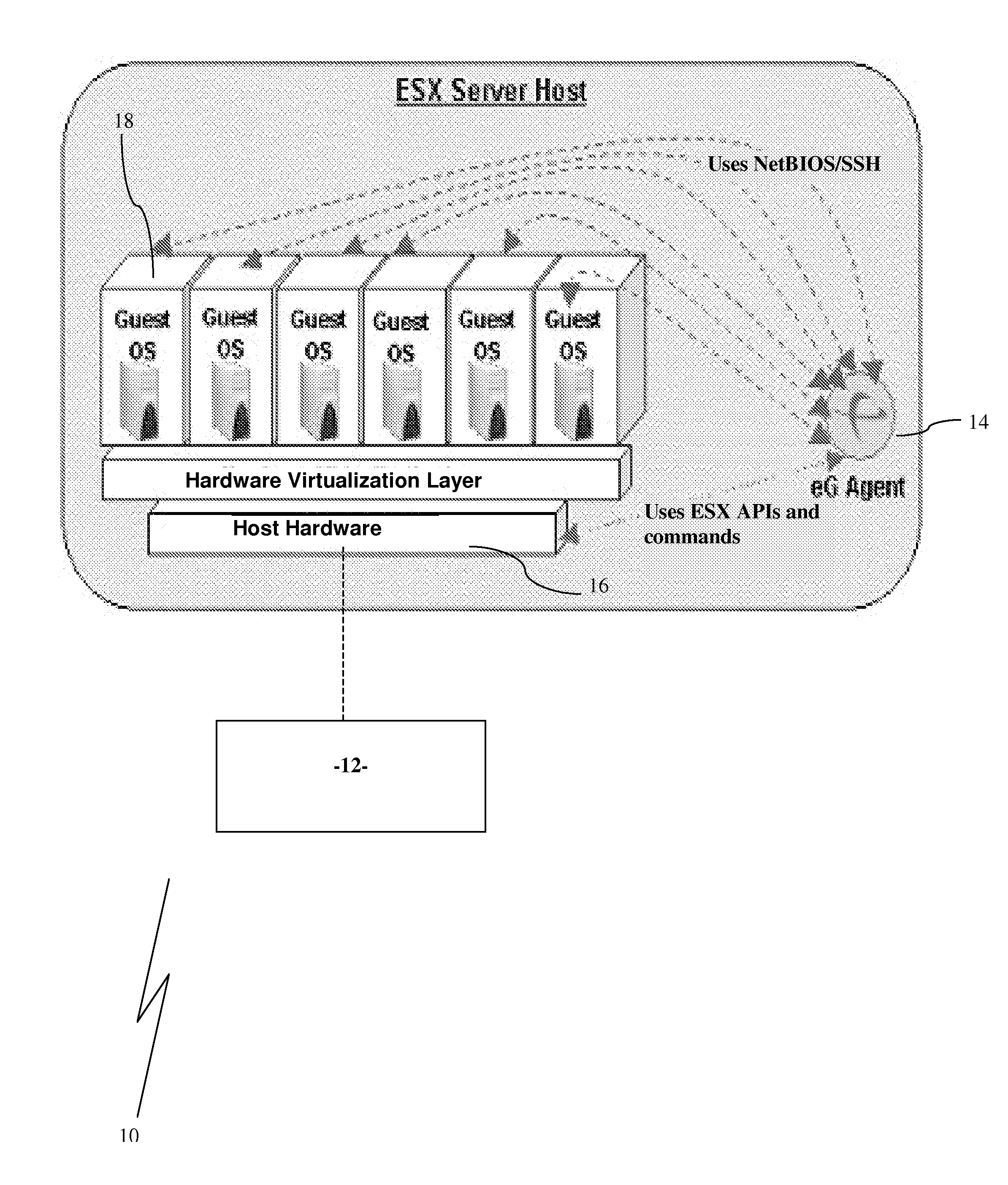
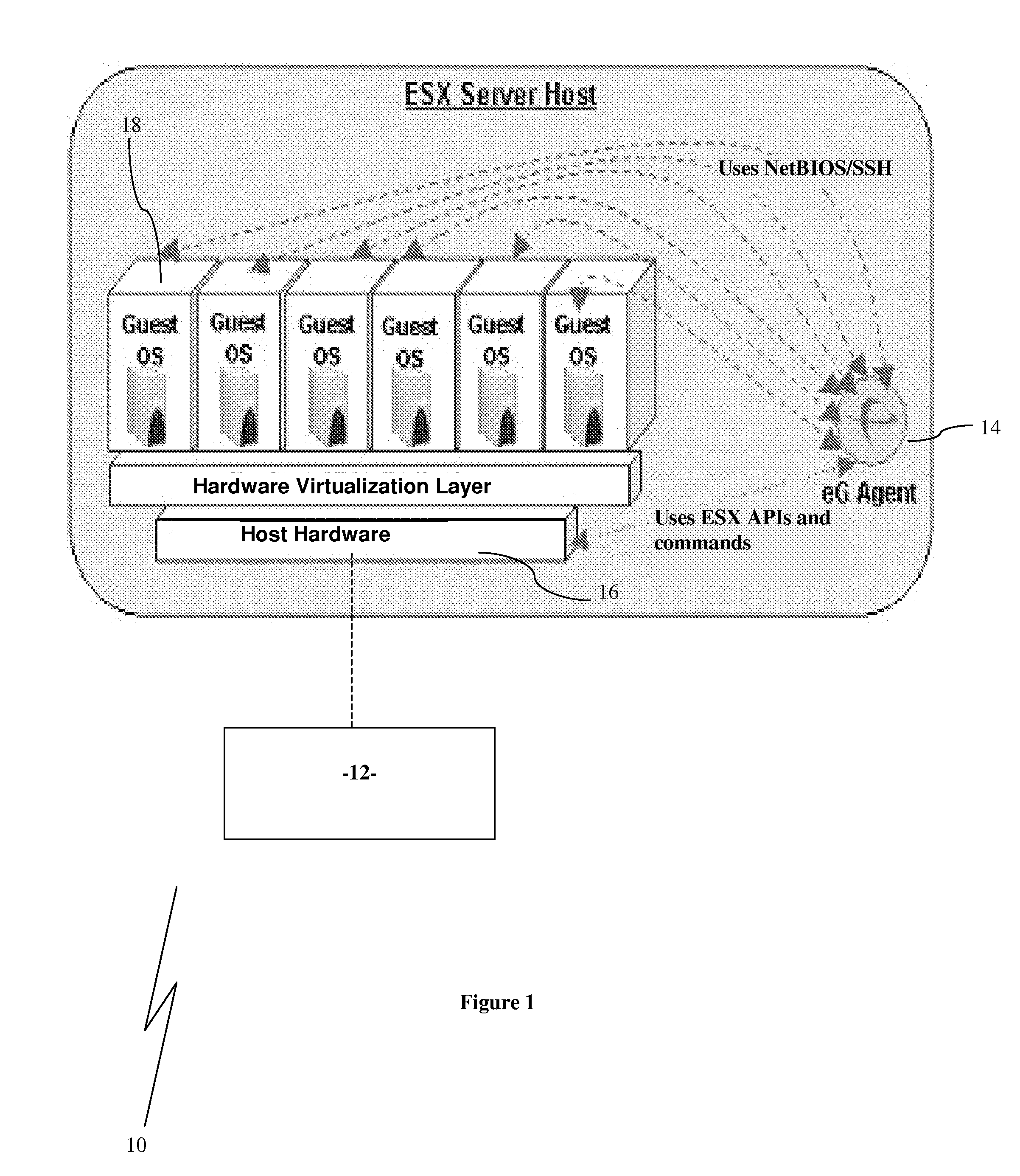
[0113]In this embodiment, virtual machines 308 to be monitored have been created on physical computer systems 306 using the VMware virtualisation software developed by VMWare, Inc of Palo Alto, Calif.

[0114]The operations and functions of the monitoring system 300 will now be described in the context of its intended use as shown in the flowcharts forming FIGS. 7 and 8. In this respect it is understood that the person skilled in the art can generate appropriate program source code to perform the described operations and functions.

[0115]On initial execution of the manager program 302, the manager program operates to d...


PUM


Abstract

A monitoring system for virtual application environments comprising: at least one physical machine executing a first operating system; at least one virtual machine operating on at least one of the at least one physical machines, each such virtual machine operating a second operating system; and an agent program operating on each of the at least one physical machines, where, each agent program is operable to obtain a first set of metrics from the first operating system, such first set of metrics including metrics in respect of each virtual machine as viewed by the first operating system, and operable to connect to the second operating system of each virtual machine hosted on the physical machine the agent program operates on and obtain a second set of metrics in respect of the virtual machine from the second operating system, the agent program further operable to communicate the first and second sets of metrics to a manager program.

Description

FIELD OF THE INVENTION[0001]The invention relates to a monitoring system for virtual application environments. The invention is particularly suited to monitoring both internal and external factors of the virtual application environments.BACKGROUND TO THE INVENTION[0002]The following discussion of the background to the invention is intended to facilitate an understanding of the present invention. However, it should be appreciated that the discussion is not an acknowledgment or admission that any of the material referred to was published, known or part of the common general knowledge in any jurisdiction as at the priority date of the application.[0003]Existing systems for monitoring virtual environments monitor the usage of critical central processing unit (“CPU”), memory and storage resources of the physical machine and characteristics of the individual virtual machines as seen from the physical machine. These latter characteristics are measured from the operating system running on t...

Claims


Application Information

Patent Timeline
IPC IPC(8): G06F9/455
CPCG06F9/45533G06F11/3409G06F2201/88G06F11/3466G06F2201/815G06F11/3419
Inventor KANNAN, RAJARAMANATHAN, SRINIVASSUBRAMANIAN, SREEDHARANVAIDHINATHAN, BALAMURUGAN
Owner EG INNOVATIONS PTE
Why Eureka
Try Eureka