Spark to flame conversion unit, such as employed with an existing spark plug or heat source supplied glow plug for accomplishing more efficient piston combustion

a conversion unit and spark technology, applied in sparking plugs, combustion air/fuel air treatment, machines/engines, etc., can solve the problems of waste of reactant, waste of energy and ignition time, and tendency of plug ignition to reactant, so as to achieve faster ionization/voltage buildup, less voltage buildup time, and faster sparking

Inactive Publication Date: 2009-01-29
FILIPEK GERALD +1
View PDF34 Cites 10 Cited by
  • Summary
  • Abstract
  • Description
  • Claims
  • Application Information

AI Technical Summary

Benefits of technology

[0009]In use with a conventional spark plug, the stf chamber encourages faster ionization / voltage buildup within the plug, resulting from such as an excising ignition coil sending a standard pulse of high voltage to the plug, with resultant faster sparking at lower temperature (e.g. again as a result of lesser voltage buildup time at the plug gap). The faster ionization and sparking (measured in one non-limiting instances ranging from such as 30% to 50%) results in decreased heat buildup and less wasted energy.
[0010]Ignition of the compressed reactants of combustion forced into stf chamber by the adjoining cylinder results in high speed jets of combusted flame being created and discharged, such as in a swirl induced pattern, through an array or peripherally (and optionally angled) output ports defined at a lower end location of the stf chamber and into the charged-compressed cylinder. In contrast to creating conventional spark ignition within the compressed cylinder, use of the stf (pre) chamber results in high speed jets of flame creating a significantly faster (both in terms of velocity and acceleration and which can also exceed 30% to 50% over existing spark plug applications) flame front (or plume), the associated burn rate delivering higher torque and power with less cycle to cycle variations.
[0011]Faster ionization results in more efficient spark to flame ignition (due to voltage buildup being delayed until a generated spark jumps the gap) and resultant faster propagation of the flame within a compressed cylinder, thereby achieving more efficient and consistent (cycle to cycle) output in combination with lower exhaust temperatures. A plurality of outlet ports are defined, such as perimeter / radially extending fashion, in an outlet end of the stf body and communicate the combusted fuels as a plurality of flame outlets with a remaining volume of atomized fuel within the combustion chamber during a power outlet stroke.
[0012]In another variant, a glow plug substitutes for the spark plug and is secured within a heat to flame (htf) pre-ignition chamber, this generally corresponding to the stf chamber utilized with the spark plug, and which in turn again defines an upper end attachable unit associated with an internal combustion cylinder. Plasma or another other high temperature heat source is communicated to the glow plug, and into the pre-chamber. Upon compression of the atomized (fuel) reactants within the associated cylinder, ignition of the heated / compressed gases occurs (typically again faster than in comparison to standard spark plug ignition) within the pre-chamber, thus igniting the gases within the compressing piston combustion chamber. A torsionally generated swirl (or again plume) is created within the pre-chamber and the created jets of flame are discharged in a rapidly accelerating and propagating fashion through the plurality of angled and perimeter defined outlets, this again resulting in more even burning (with reduced emissions), consistent power output (cycle to cycle) with higher efficiency / lower exhaust temperature.

Problems solved by technology

This action results in both wasted energy and ignition time.
Known disadvantages associated with conventional spark plugs include the tendency of the plug ignition to reactant combustion firing timing often being out of step with an optimal (near or at) top dead center position established between the piston driven cylinder bead and cylinder.
Other disadvantages associated with conventional spark plug ignition includes the tendency of the subsequent cylinder combustion to occur incompletely, resulting in wasted reactants discharged through the cylinder exhaust cycle and less than optimal power delivery to the crankshaft or other work output mechanism connected to the cylinder head connected crank.

Method used


Image

  • Spark to flame conversion unit, such as employed with an existing spark plug or heat source supplied glow plug for accomplishing more efficient piston combustion
  • Spark to flame conversion unit, such as employed with an existing spark plug or heat source supplied glow plug for accomplishing more efficient piston combustion
  • Spark to flame conversion unit, such as employed with an existing spark plug or heat source supplied glow plug for accomplishing more efficient piston combustion

Examples


Embodiment Construction

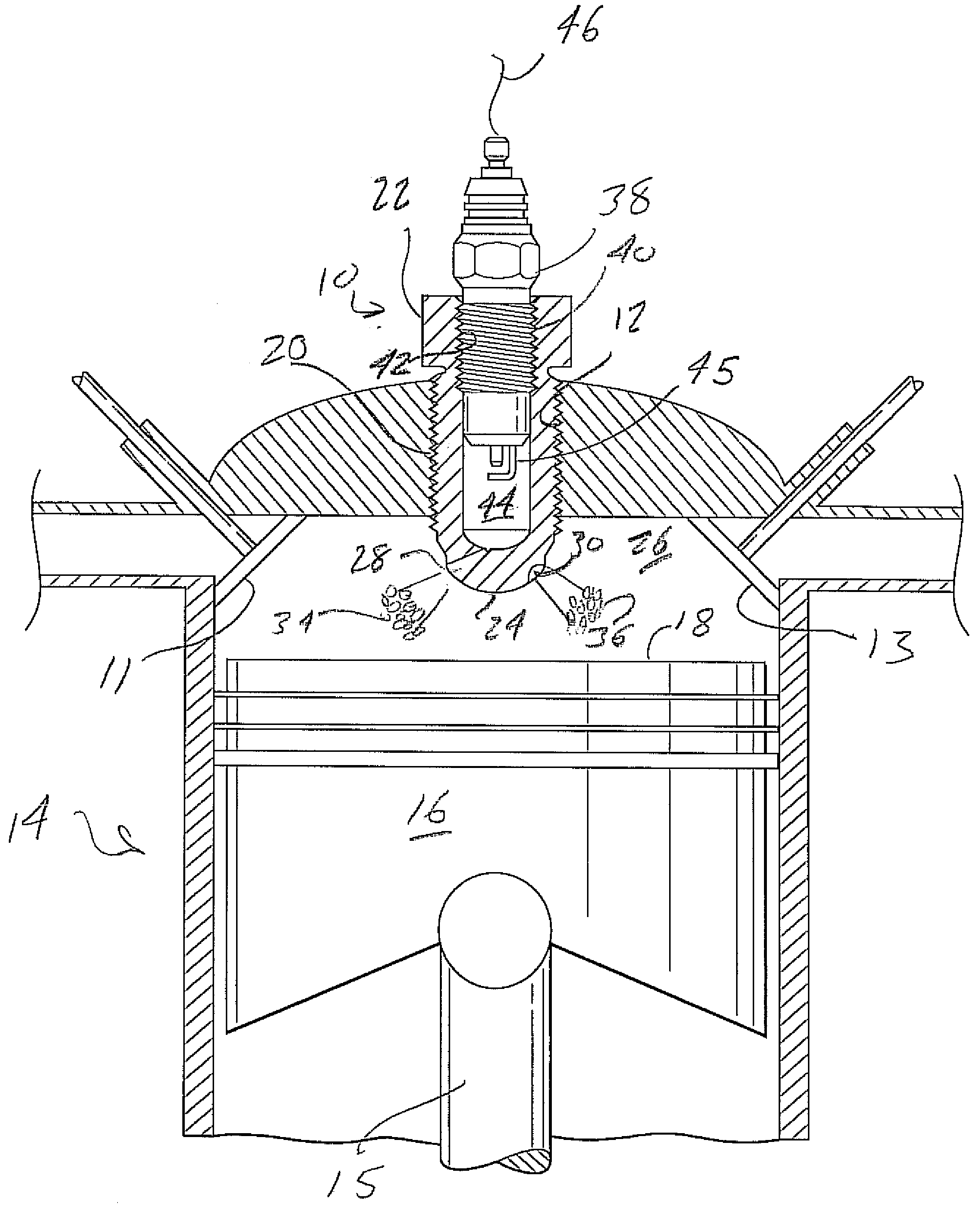
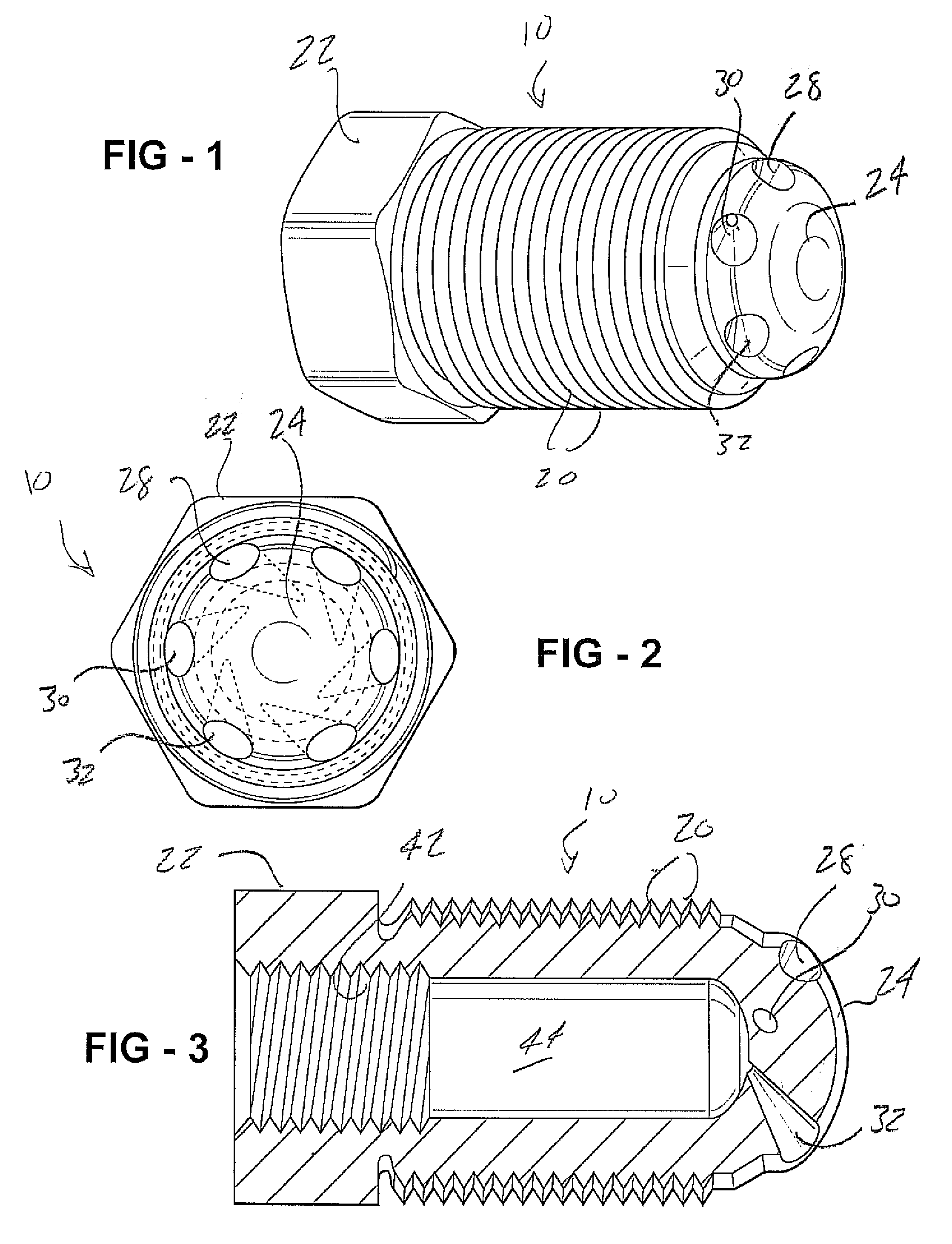
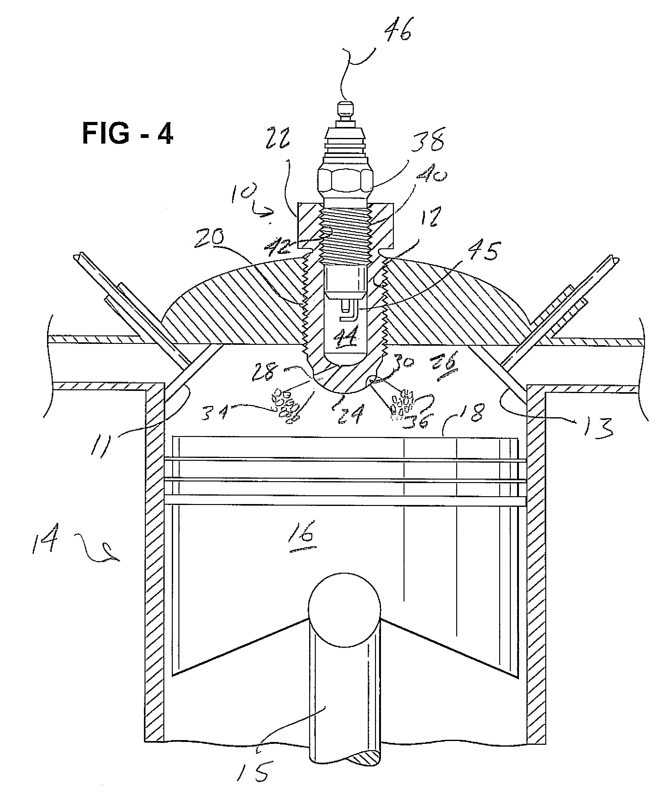
[0020]As described previously, the present invention is directed to devices and techniques for achieving faster ionization of a spark generating plug or other heat input source such as associated with a glow plug or the like. More particularly, and as will be described in further detail below, the present inventions are directed to applications including either a spark to flame (stf) pre-chamber (FIGS. 1-4) or a heat to flame (htf) pre-chamber (FIGS. 5 and 6A-6C) secured to an upper end location of a cylinder associated with an internal combustion engine. As will also be described in additional detail, the spark to flame or heat to flame pre-chamber bodies are each capable of being threadably, or otherwise, engaged into a top end location of a combustion chamber and, in use, igniting a compressed and atomized fuel such as ethanol, various octane grades of gasoline, diesel, bio-fuels or the like, to cause faster, more even burning ignition and flame / plume propagation resulting in inc...


PUM


Abstract

A pre-chamber for use with a spark plug or glow plug, the chamber being secured at an upper end attachable unit associated with an internal combustion cylinder. The pre-chamber is designed to promote faster ionization resulting in more efficient spark to flame ignition (due to voltage buildup being delayed until a generated spark jumps the gap), or beat to flame ignition (due to the introduction temperature of the injected plasma) and, in each instance, results in faster propagation of flame within the compressed cylinder, thereby achieving more efficient and consistent (cycle to cycle) output in combination with lower exhaust temperatures. A plurality of outlet ports are defined, such as perimeter / radially extending fashion, in an outlet end of the pre chamber body and communicate the combusted fuels as a plurality of flame outlets with a remaining volume of atomized fuel within the combustion chamber during a power outlet stroke.

Description

CROSS-REFERENCE TO RELATED APPLICATIONS[0001]This Application is a Non-Provisional of Provisional (35 USC 119(e)) application 60 / 951,866 filed on Jul. 25, 2007.FIELD OF THE INVENTION[0002]The present inventions are directed to devices and techniques for achieving faster ionization of a spark generating plug or other heat input source such as associated with a glow plug or the like. The spark plug or glow plug is secured within a spark to flame (stf) pre-ignition chamber, this in turn defining an upper end attachable unit associated with an internal combustion cylinder. In this instance of a spark plug, faster ionization results in more efficient spark to flame ignition (due to voltage buildup being delayed until a generated spark jumps the gap) and resultant faster propagation of the flame within a compressed cylinder, thereby achieving more efficient and consistent (cycle to cycle) output in combination with lower exhaust temperatures. A plurality of outlet ports are defiled, such ...

Claims


Application Information

Patent Timeline
Patent Type & Authority Applications(United States)
IPC IPC(8): F02P15/00F02P21/00
CPCF02B23/0657Y02T10/125F02P15/06F02M27/042Y02T10/12
Inventor FILIPEK, GERALDPLANTRICH, MARK
Owner FILIPEK GERALD
Why Eureka
Try Eureka