
Sheet conveying device, and image forming apparatus including same

Inactive Publication Date: 2009-01-29
RICOH KK
View PDF6 Cites 28 Cited by
  • Summary
  • Abstract
  • Description
  • Claims
  • Application Information

AI Technical Summary

Benefits of technology

[0015]In light of the foregoing, the inventors of the present patent application previously propose to provide a sheet conveying device and an image forming apparatus including a sheet conveying device that can eliminate the drawbacks of the above-described techniques, specifically, by providing a sheet conveying device that is compact and space-saving, that includes a simple configuration achieved at low cost, that can handle various types of sheets, and that can reserve or secure sufficient distance and space for bending a leading edge of a sheet, and an image forming apparatus that includes such sheet conveying device.

Problems solved by technology

However, when a recording medium having a certain critical thickness enters the secondary transfer area, the speed of the intermediate transfer member may decrease for a short period of time.
Accordingly, an intermediate transfer unit including the intermediate transfer member may transmit a brief decrease in speed caused in the secondary transfer area and cause deviations or defects in images in the primary transfer area.
In such a configuration, however, the fixing unit suffers from the same drawback as the intermediate transfer unit.
Specifically, when a sheet-type recording medium having a certain thickness enters the secondary transfer area, a fixing roller or belt driven at a constant speed in the fixing unit may experience a brief decrease in speed, thereby transmitting the brief decrease via the fixing unit and causing deviations or defects in images in the secondary transfer area.
However, changes in the amount of such speed control are abrupt, and can be modeled as rectangular waveforms.
However, such control requires an additional mechanism to adjust the pressing force, which causes an increase in costs.
In addition, it is mechanically difficult to accurately control the pressing force.

Method used


Image

  • Sheet conveying device, and image forming apparatus including same
  • Sheet conveying device, and image forming apparatus including same
  • Sheet conveying device, and image forming apparatus including same

Examples


Embodiment Construction

[0041]It will be understood that if an element or layer is referred to as being “on”, “against”, “connected to” or “coupled to” another element or layer, then it can be directly on, against, connected or coupled to the other element or layer, or intervening elements or layers may be present. In contrast, if an element is referred to as being “directly on”, “directly connected to” or “directly coupled to” another element or layer, then there are no intervening elements or layers present. Like numbers referred to like elements throughout. As used herein, the term “and / or” includes any and all combinations of one or more of the associated listed items.

[0042]Spatially relative terms, such as “beneath”, “below”, “lower”, “above”, “upper” and the like may be used herein for ease of description to describe one element or feature's relationship to another element(s) or feature(s) as illustrated in the figures. It will be understood that the spatially relative terms are intended to encompass...


PUM


Abstract

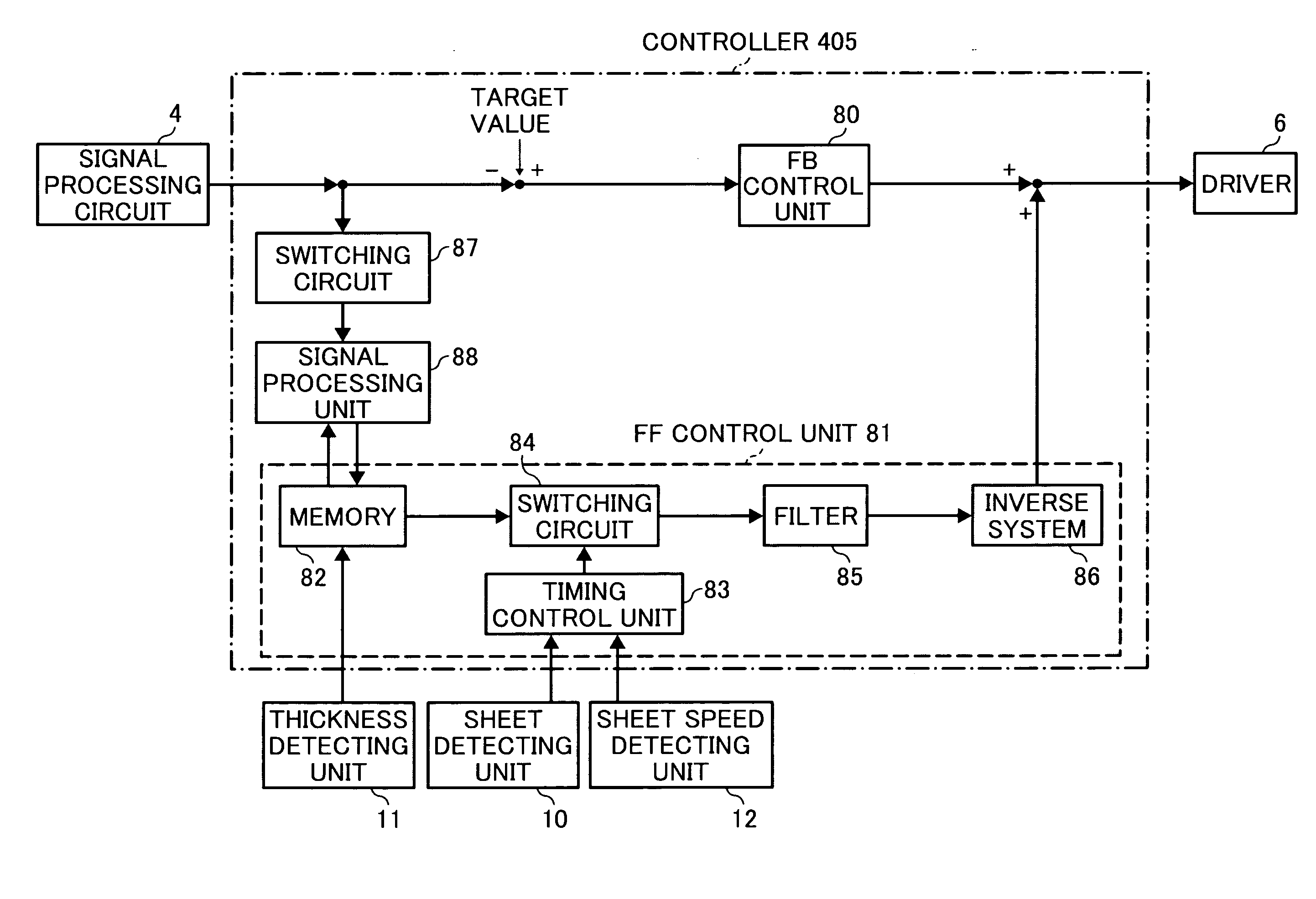
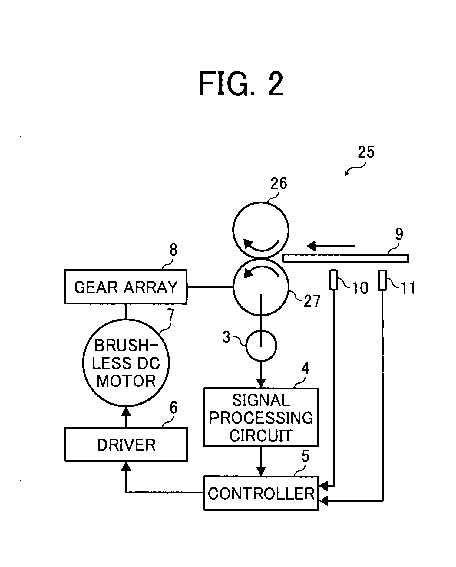
A sheet conveying device, that can be included in an image forming apparatus, includes a drive source, a drive roller driven by the drive source, a driven roller to press against the drive roller and rotate with the drive roller, an angular velocity detector to detect an angular velocity of the drive roller, a timing estimation unit to estimate a timing when a sheet-type recording medium enters between the drive roller and the driven roller, and a controller to control the drive source based on detection results obtained by the angular velocity detector. The controller includes a feedback control unit to perform feedback control based on data obtained by the angular velocity detector, and a feed-forward control unit to perform feed-forward control based on data obtained by the timing estimation unit.

Description

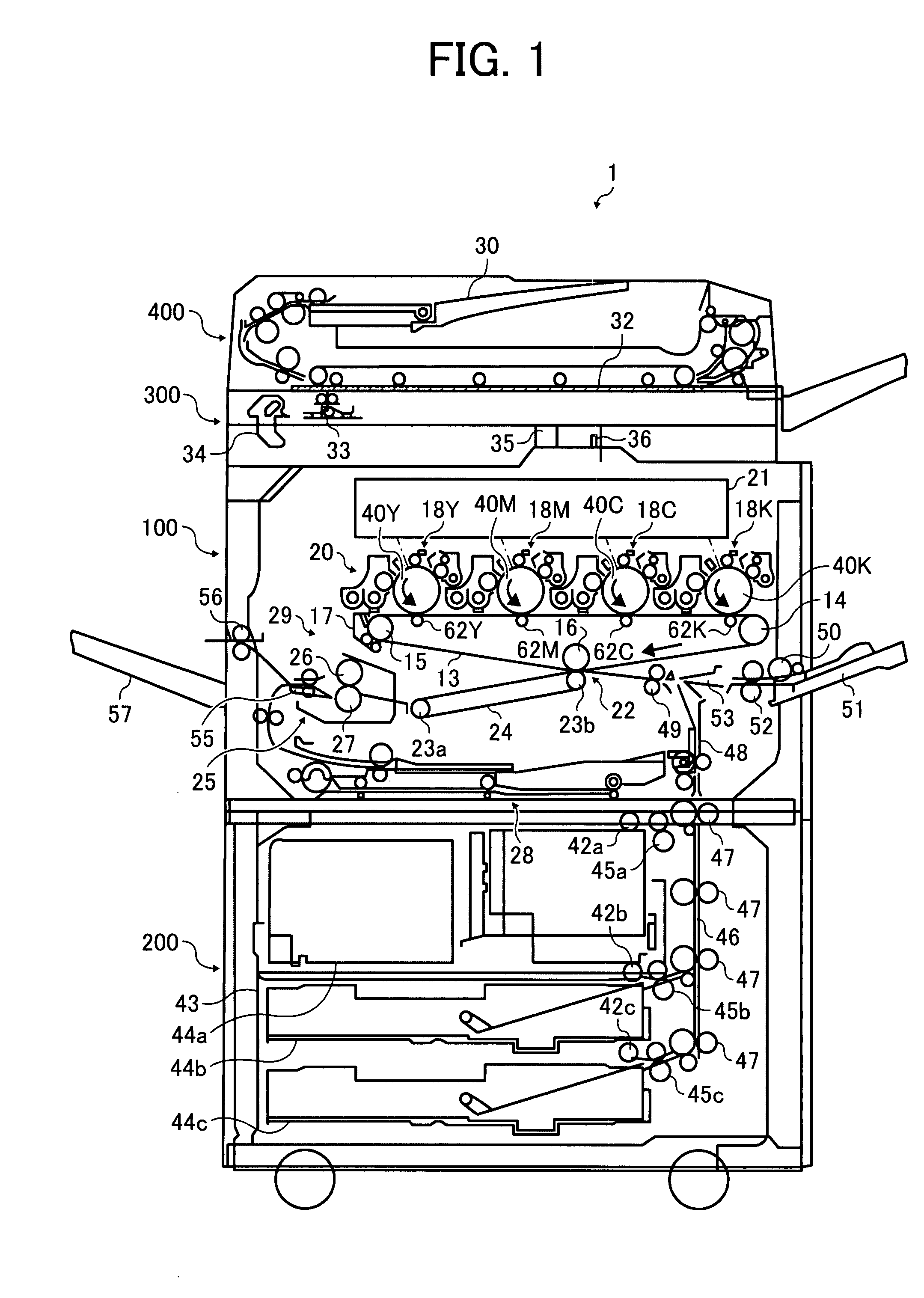
PRIORITY STATEMENT[0001]The present patent application claims priority under 35 U.S.C. §119 from Japanese Patent Application No. 2006-279413 filed on Oct. 13, 2006, the contents and disclosures of which are hereby incorporated by reference herein in their entirety.BACKGROUND[0002]1. Field[0003]Example embodiments of the present patent application generally relate to a sheet conveying device and an image forming apparatus including the sheet conveying device. More particularly, the present patent application relates to a sheet conveying device conveying a sheet-type recording medium between a drive roller and a driven roller contacting the drive roller with pressure, and an image forming apparatus including the sheet conveying device therein.[0004]2. Discussion of the Related Art[0005]Electrophotographic image forming apparatuses rotate a drum-shaped or belt-shaped photoconductor to charge a surface thereof and optically write an electrostatic latent image on the surface. Toner is su...

Claims


Application Information

Patent Timeline
IPC IPC(8): B65H7/02
CPCB65H5/062B65H7/20B65H2513/50B65H2553/51B65H2801/06G03G15/657G03G2215/00738G03G2215/00949G03G2215/00746B65H2220/03B65H2220/01B65H2220/11
Inventor NOGUCHI, HIDETAKAMATSUDA, HIROMICHIANDOH, TOSHIYUKI
Owner RICOH KK
Learn More