Hydraulic Braking Device

a technology of hydraulic braking and brake pedal, which is applied in the direction of braking systems, braking components, transportation and packaging, etc., can solve the problem of not knowing whether an appropriate brake force can be generated, and achieve the effect of increasing the operability of the brake pedal

Inactive Publication Date: 2009-01-29
HITACHI LTD
View PDF13 Cites 32 Cited by
  • Summary
  • Abstract
  • Description
  • Claims
  • Application Information

AI Technical Summary

Benefits of technology

[0013]According to the present invention, even when a driver executes a brake operation during the automatic braking, it is possible to genera

Problems solved by technology

However, in a conventional configuration mentioned above, operation of the second operating member has not been disclosed in cases in which the first operating member is acted upon by a driver's braking operation when the second operating m

Method used


Image

  • Hydraulic Braking Device
  • Hydraulic Braking Device
  • Hydraulic Braking Device

Examples


embodiment 1

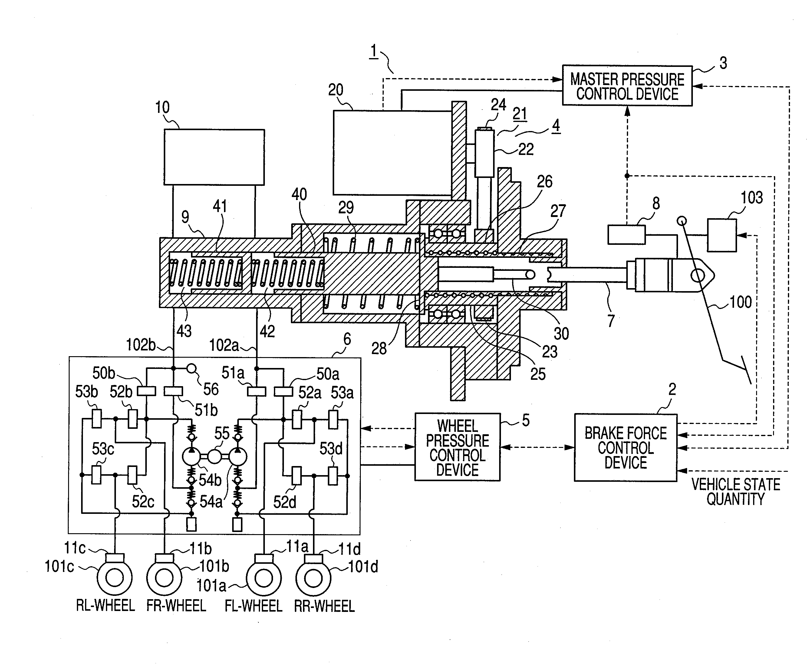
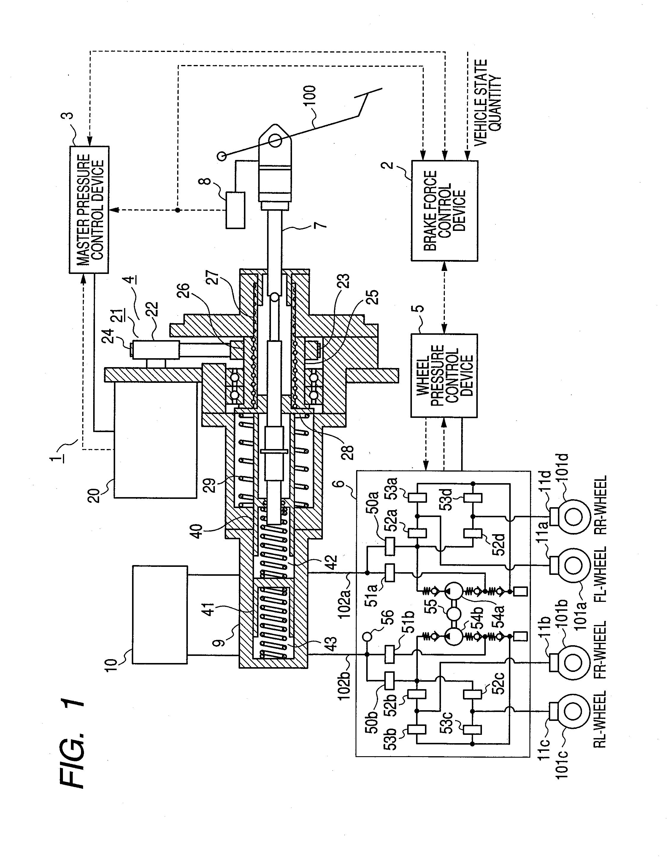
[0039]FIG. 1 is a schematic drawing showing an entire configuration of a hydraulic braking device 1 according to a first embodiment of the present invention. The FL-wheel indicates the left front wheel, the FR-wheel indicates the right front wheel, the RL-wheel indicates the left rear wheel, and the RR-wheel indicates the right rear wheel. Furthermore, the broken line with an arrow is a signal line, showing that the signal flows in the direction of the arrow.

[0040]As shown in FIG. 1, the hydraulic braking device 1 comprises a brake force control device 2 which functions as a brake force control means, a master pressure control device 3 and a master pressure control mechanism 4 both of which function as a second pressurizing and depressurizing means, a wheel pressure control device 5, a wheel pressure control mechanism 6, an input rod 7 which functions as a first pressurizing and depressurizing means, a brake sensor 8, a master cylinder 9, a reservoir 10, and wheel cylinders 11a-d. F...

embodiment 2

[0171]FIG. 6 is a schematic drawing showing an entire configuration of a hydraulic braking device 1 according to a second embodiment of the present invention. The same number is assigned to the same portion as that of the first embodiment and description is omitted.

[0172]The second embodiment differs from the first embodiment in that the input rod 7 is not inserted into the primary chamber 42; the conveying member 30 is connected to the moving member 28; the input rod 7 and the conveying member 30 are disposed with a certain gap; and the reaction force generation mechanism 103 is connected to the brake pedal 100. Herein, the reaction force generation mechanism 103 generates a prescribed reaction force according to a control command from the brake force control device 2 and makes the reaction force act upon the brake pedal 100.

[0173]That is, the first routine executed by the brake force control device 2 and the primary piston 40 control executed by the second routine are the same as ...


PUM


Abstract

The first control is to displace the primary piston by the amount obtained by multiplying the input rod displacement quantity by a proportional gain. The second control is to propel the primary piston by a prescribed offset thereby executing the first control. The third control is to displace the primary piston by the amount obtained by multiplying the input rod displacement quantity by a proportional gain specifically at a pressure decrease request. The brake force control device properly selects a control method from the first to third control methods to control the primary piston based on the automatic braking release conditions and a driver's brake request when a driver executes a brake operation during the automatic braking.

Description

CLAIM OF PRIORITY[0001]The present application claims priority from Japanese patent application serial No. 2007-195317, filed on Jul. 27, 2007, the content of which is hereby incorporated by reference into this application.FIELD OF THE INVENTION[0002]The present invention relates to a hydraulic braking device which controls a brake force by controlling the working fluid pressure operating at each wheel cylinder of a vehicle.BACKGROUND OF THE INVENTION[0003]As a configuration for executing automatic braking by pressurizing and depressurizing a master cylinder independently of a brake pedal operation, a conventional configuration has been disclosed wherein an idling distance is provided between a first operating member, such as a brake pedal or a member indirectly connected to a brake pedal, and a second operating member connected downstream of the flow of the force of an input member in order to mechanically separate the first operating member from the reaction of the force of the au...

Claims


Application Information

Patent Timeline
IPC IPC(8): B60T13/66
CPCB60T7/12B60T13/745B60T13/662B60T8/4077
Inventor MATSUBARA, KENICHIROINNAMI, TOSHIYUKIYOKOYAMA, ATSUSHIKURAGAKI, SATORUNISHINO, KIMIOSUGAWARA, TOSHIHARU
Owner HITACHI LTD
Why Eureka
Try Eureka