
Display device and driving method

a liquid crystal display and driver technology, applied in the direction of electric digital data processing, instruments, computing, etc., can solve the problems of increasing the probability of manufacturing defects, hindering the ever present goal of size reduction in integrated circuits, and requiring a buffer of 110 KB, so as to facilitate the transfer of the same amount of video data, facilitate the spread of unused frame time, and facilitate the effect of driving different portions of an imager's display

Active Publication Date: 2009-01-29
OMNIVISION TECH INC
View PDF94 Cites 57 Cited by
  • Summary
  • Abstract
  • Description
  • Claims
  • Application Information

AI Technical Summary

Benefits of technology

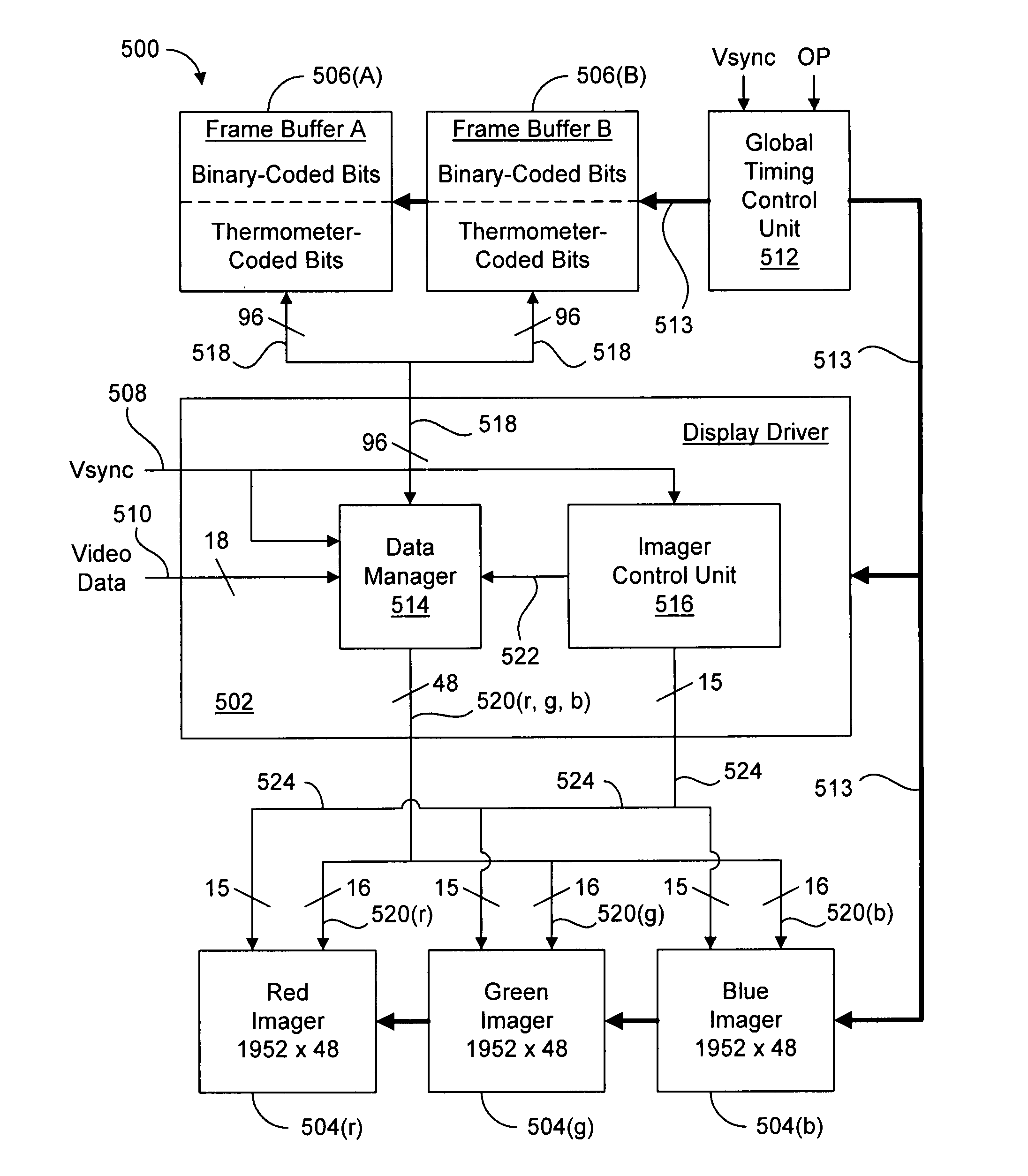
[0022]The present invention overcomes the problems associated with the prior art by providing a display driver and method that equalizes the bandwidth between the display driver and the imager over the entire frame. The invention facilitates transferring the same amount of video data during each time interval within a frame by setting the number of time intervals equal to an integer multiple of the number of rows in the display. By equalizing the bandwidth, the power requirements needed to update the pixels in the display are equalized over the frame. The invention also facilitates spreading any unused frame time over the entire frame based on the number of row updates performed during the frame. Furthermore, the invention facilitates driving different portions of an imager's display with different iterations of pixel control circuitry, thereby enabling more intensity values to be defined by each pixel in the display.
[0027]According to another aspect of the present invention where the imager(s) contain (s) iterations of pixel control units and the rows are allocated among (s) sets of rows, then the following additional limitations on the bit code of the data words also apply. First, the sum of the weighted values in each data word should be evenly divisible by s*n, where (s) equals the number of iterations of pixel control circuitry in the imager(s) and (n) is given above. Second, the number of bits in each data word should be evenly divisibly by s*n. Third, an equal number of rows assigned to each of the (s) sets should be updated by each pixel control circuitry unit. This aspect of the invention increases the processing capability of the imagers because each imager can process more data instructions because of the multiple pixel control units.
[0036]Another aspect of the present invention facilitates 100% bandwidth and operation efficiency during each time interval in a frame. A particular method for driving an array of pixels includes the steps of defining a plurality of modulation periods during which electrical signals corresponding to particular intensity values will be asserted on pixels in rows of the array, associating each modulation period with at least one of the rows in the array, and then dividing each of the modulation periods into a plurality of coequal time intervals. In addition, the method also includes the steps of receiving a plurality of multi-bit data words that are each indicative of one of the intensity values that is asserted on a corresponding pixel and updating the electrical signals asserted on the pixels in an equal number of rows during each time. Usually less than all of the rows in the array are updated during each time interval. In a particular method, (b / n) rows are updated during each time interval, where b equals the number of bits in each multi-bit data word.
[0038]Yet another aspect of the present invention facilitates spreading any unused frame time between the time intervals in a modulation time period, thereby increasing the length of the time intervals. In particular, the method includes receiving a first synchronization signal, defining a time period during which electrical signals corresponding to intensity values will be asserted on pixels of an array, updating the electrical signals on the pixels a plurality of times during the time period such that each pixel displays the corresponding intensity value, and receiving a second synchronization signal that defines a time difference between the last time the electrical signals in a row were updated and the receipt of the second frame synchronization signal. The method further includes the steps of defining a second time period during which electrical signals will be asserted on the pixels in the rows of the array, updating the electrical signals asserted on the pixels in the rows a plurality of times during the second time period such that each of the pixels displays the corresponding intensity value, and spreading the time difference throughout the second time period based upon the number of times the electrical signals asserted on pixels in the rows of the display are updated during the second time period. Spreading the time difference throughout the second time period adjusts the duration of at least some of the time intervals in the second time period.

Problems solved by technology

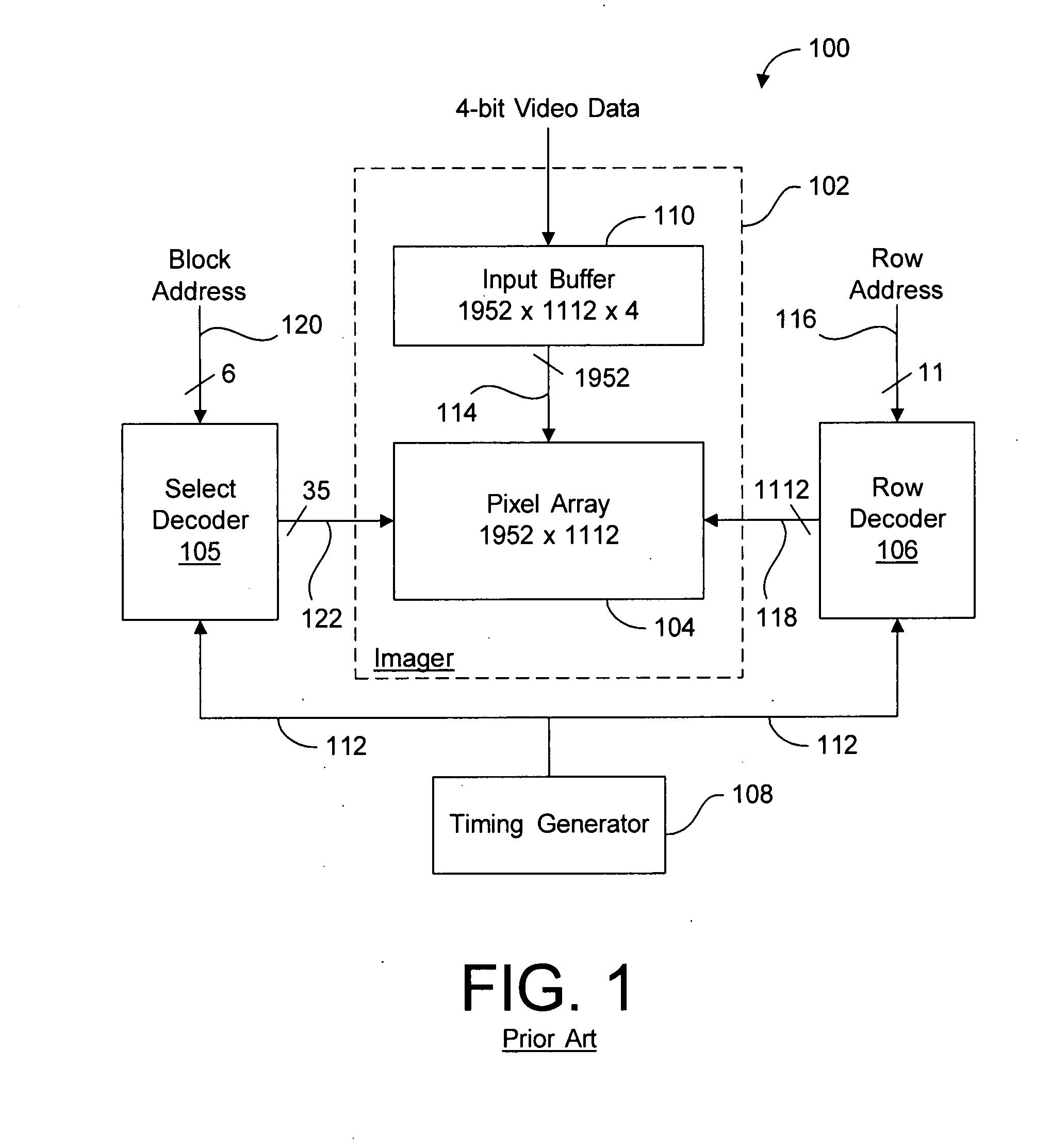
The size requirement of input buffer 110 is a significant disadvantage.
As the required memory capacity increases, the chip space required by input buffer 110 also increases, thus hindering the ever present objective of size reduction in integrated circuits.
Further, as the memory capacity increases, the number of storage devices increases, thereby increasing the probability of manufacturing defects, which reduces the yield of the manufacturing process and increase the cost of imager 102.
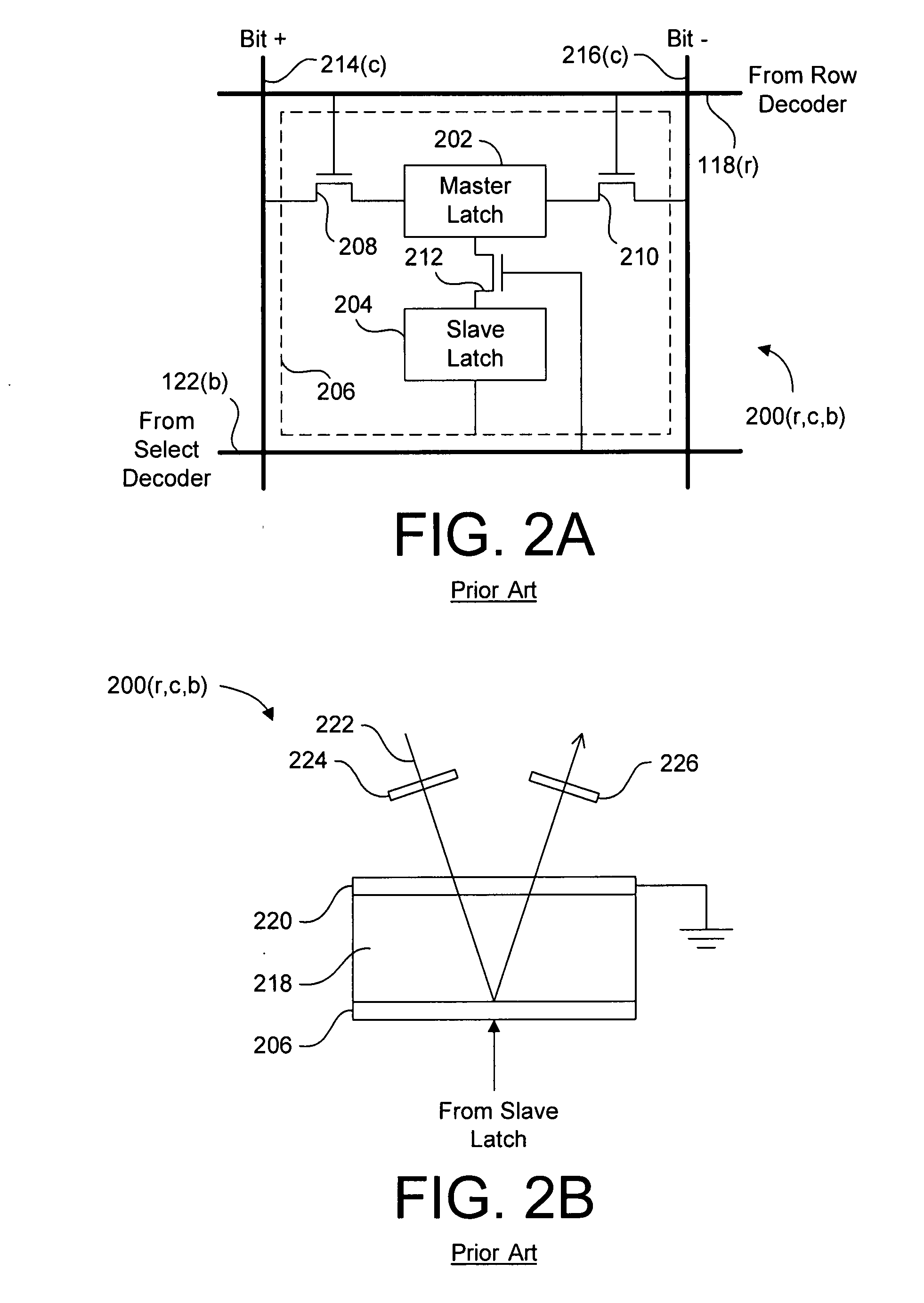
Although the master-slave latch design functions well, it is a disadvantage that each pixel cell requires two storage latches.
It is also a disadvantage that separate circuitry is required to write data to the pixel cells and to cause the stored data to be asserted on the pixel electrode.
The cell rise time can cause undesirable visual artifacts in the image produced by pixel array 104 such as blurred moving objects and / or moving objects that leave ghost trails.
Further, visually perceptible aberrations result from the assertion of opposite digital values on adjacent pixel electrodes for a significant portion of the frame time, at least in part to the lateral field affect between adjacent pixels.

Method used


Image

  • Display device and driving method
  • Display device and driving method
  • Display device and driving method

Examples


Embodiment Construction

[0105]This application discloses subject matter which is similar to the following co-pending U.S. patent applications Ser. No., which are incorporated herein by reference in their entireties.

[0106]U.S. patent application Ser. No. 11 / 154,984, filed on Jun. 16, 2005, and entitled “Asynchronous Display Driving Scheme and Display”;

[0107]U.S. patent application Ser. No. 11 / 171,496, filed on Jun. 30, 2005, and entitled “Single Pulse Display Driving Scheme and Display”;

[0108]U.S. patent application Ser. No. 11 / 172,622, filed on Jun. 30, 2005, and entitled “System and Method for Discarding Data Bits During Display Modulation”;

[0109]U.S. patent application Ser. No. 11 / 172,621, filed on Jun. 30, 2005, and entitled “Display Driving Scheme and Display”;

[0110]U.S. patent application Ser. No. 11 / 172,382, filed on Jun. 30, 2005, and entitled “Display Debiasing Scheme and Display”; and

[0111]U.S. patent application Ser. No. 11 / 172,623, filed on Jun. 30, 2005, and entitled “System and Method for Usin...


PUM


Abstract

A novel method for driving a display having an array of pixels arranged in a plurality of columns and a plurality of rows includes the steps of defining a modulation period for a row of pixels, dividing the modulation period into a number of coequal time intervals equal to n times the number of rows in the array, receiving a multi-bit data word that indicates an intensity value, and updating the signal asserted on the pixel during a plurality of the time intervals such that the intensity value is displayed by the pixel. Note that n is an integer greater than zero. The method can be applied to all rows, which can be driven asynchronously. A display driver for performing the novel methods is also disclosed. The present invention facilitates driving the display at 100% bandwidth efficiency during each time interval in the modulation period.

Description

BACKGROUND[0001]1. Field of the Invention[0002]This invention relates generally to driving electronic displays, and more particularly to a display driver circuit and methods for driving a multi-pixel liquid crystal display. Even more particularly, the present invention relates to a driver circuit and method for driving a liquid crystal on silicon display device with a digital backplane.[0003]2. Description of the Background Art[0004]FIG. 1 shows a block diagram of a prior art display driver 100 for driving an imager 102, which includes a pixel array 104 having 1952 columns and 1112 rows. Display driver 100 also includes a select decoder 105, a row decoder 106, and a timing generator 108. In addition to pixel array 104, imager 102 also includes an input buffer 110, which receives and stores 4-bit video data from a system (e.g., a computer that is not shown). Timing generator 108 generates timing signals by methods well known to those skilled in the art, and provides the timing signal...

Claims


Application Information

Patent Timeline
IPC IPC(8): G06F3/038
CPCG09G3/20G09G3/2022G09G2310/0272G09G2310/0235G09G2310/0267G09G5/395
Inventor KWAN, KIN YIP KENNETHNGUYEN, ANDREANG, SUNNY YAT-SANZURAVLEFF, WILLIAM K.
Owner OMNIVISION TECH INC
Learn More