Image Processing for Estimating Subject Distance

Inactive Publication Date: 2009-01-29
SEIKO EPSON CORP
View PDF5 Cites 5 Cited by
  • Summary
  • Abstract
  • Description
  • Claims
  • Application Information

AI Technical Summary

Benefits of technology

[0015]In the image processing method according to the second application example, the execution of the specific process may include, as the specific process, executing a blurring process on an image in a predetermined background area in the target image, and setting a blurring degree in the blurring process on the basis of the estimated subject distance so as to increase the blurring degree when the subject distance is small.
[0020]According to the above image processing method, it is possible to reduce time required for focusing.SEVENTH APPLICATION EXAMPLE

Problems solved by technology

However, a method of estimating the subject distance of an image has not been known.

Method used


Image

  • Image Processing for Estimating Subject Distance
  • Image Processing for Estimating Subject Distance
  • Image Processing for Estimating Subject Distance

Examples


first example embodiment

A. First Example Embodiment

A-1. Configuration of Image Processing Device

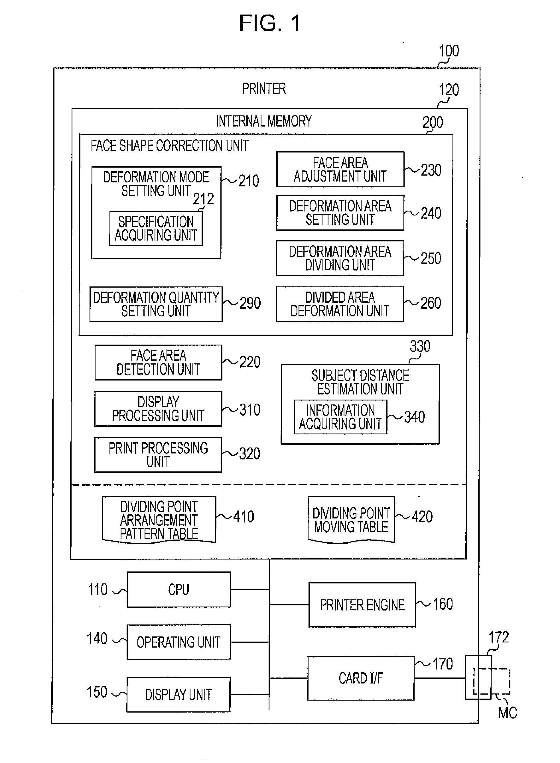
[0083]FIG. 1 is a block diagram that schematically illustrates the configuration of a printer 100, which serves as an image processing device, according to a first example embodiment of the invention. The printer 100 of the first example embodiment is a color ink jet printer that is able to print out an image on the basis of image data acquired from a memory card MC, or the like, which is so-called direct print. The printer 100 includes a CPU 110, an internal memory 120, an operating unit 140, a display unit 150, a printer engine 160, and a card interface (card I / F) 170. The CPU 110 controls portions of the printer 100. The internal memory 120 is, for example, formed of ROM and / or RAM. The operating unit 140 is formed of buttons and / or a touch panel. The display unit 150 is formed of a liquid crystal display. The printer 100 may further include an interface that performs data communication with other devices (fo...

second example embodiment

B. Second Example Embodiment

[0208]FIG. 36 is a view that schematically illustrates the configuration of a printer 100a, which serves as an image processing device, according to a second example embodiment of the invention. The printer 100a according to the second example embodiment differs from the printer 100 (FIG. 1) according to the first example embodiment in that the printer 100a according to the second example embodiment includes a blur processing unit 360 in place of the face shape correction unit 200. The remaining configuration of the printer 100a according to the second example embodiment is the same as that of the printer 100 according to the first example embodiment.

[0209]The blur processing unit 360 is a computer program that executes background blur printing process, which will be described later, under a predetermined operating system. The blur processing unit 360 includes a blurring degree setting unit 362.

[0210]FIG. 37 is a flowchart of the background blur printing ...

third example embodiment

C. Third Example Embodiment

[0220]FIG. 41 is a view that schematically illustrates the configuration of a digital still camera 500, which serves as an image processing device, according to a third example embodiment of the invention. The digital still camera (hereinafter, referred to as “DSC”) 500 according to the third example embodiment functions as an image pickup apparatus (image generating device) that generates an image by imaging an object and functions as an image processing device that executes image processing on the generated image.

[0221]The DSC 500 includes a lens 502, a lens driving unit 504, a lens drive control unit 506, an image pickup device 508, an A / D converter 510, an interface unit (I / F unit) 512, a display unit 514, an operating unit 516, a CPU 518, and an internal memory 600. The lens driving unit 504 adjusts the position of a focal point (focus) and the focal length by driving the lens 502. The lens drive control unit 506 controls the lens driving unit 504. Th...


PUM


Abstract

An image processing method includes acquiring first information that indicates a size of an image of a specific subject in a target image relative to a size of the target image, acquiring second information that indicates a size of the specific subject, acquiring third information with which an angle of view of the target image can be determined, and estimating a subject distance, which is a distance from an image pickup apparatus that has generated the target image to the specific subject on the basis of the first information, the second information and the third information.

Description

CROSS-REFERENCE TO RELATED APPLICATIONS[0001]This application claims the benefit of priority under 35 USC 119 in Japanese application no. 2007-192459, filed on Jul. 24, 2007, which application is incorporated by reference in its entirety.BACKGROUND[0002]1. Technical Field[0003]The invention relates to an image processing technology for estimating a subject distance.[0004]2. Related Art[0005]An image processing technology for deforming a digital image has been known and is described, for example, in JP-A-2004-318204. JP-A-2004-318204 describes an image processing that deforms the shape of a face in such a manner that part of an area on the image of a face (the area that shows the image of a cheek, for example) is set as a correction area. The correction area is divided into a plurality of small areas in accordance with a predetermined pattern, and the image is enlarged or reduced with a scaling factor set for each small area.[0006]Incidentally, the impression obtained by observing an...

Claims


Application Information

Patent Timeline
IPC IPC(8): G06K9/00
CPCG06K9/00228G06T2207/20144G06T2200/24G06T5/002G06T7/194G06V40/161G06T5/70
Inventor HAYAISHI, IKUO
Owner SEIKO EPSON CORP
Why Eureka
Try Eureka