Fixing apparatus, heating roller, and image forming device

a technology of fixing apparatus and heating roller, which is applied in the direction of electrographic process apparatus, instruments, optics, etc., can solve the problems of reducing affecting the service life of the heat-producing roller, so as to reduce the amount of heat lost, prevent offset, and reduce the effect of heat loss

Inactive Publication Date: 2009-01-29
PANASONIC CORP
View PDF8 Cites 29 Cited by
  • Summary
  • Abstract
  • Description
  • Claims
  • Application Information

AI Technical Summary

Benefits of technology

[0037]According to the present invention, by using a magnetic material whose Curie temperature at which magnetism disappears when a predetermined temperature or higher is reached has been adjusted, and that has undergone annealing treatment at 600° C. or higher after shaping processing as an endless belt, roller, or the like of uniform thickness, an excessive rise in temperature and the occurrence of offset can be prevented, and good fixing capability can be realized, in an electromagnetic heating type of fixing apparatus.
[0038]Also, according to the present invention, an excessive rise in temperature when narrow recording material is fed through continuously is surely prevented, and the warm-up time is shortened, and furthermore shortening of the fixing apparatus life, the occurrence of offset, and so forth, due to an excessive rise in temperature can be prevented, and good fixing capability can be realized.

Problems solved by technology

However, as recording materials that pass through the nip may be of various widths, heat is not necessarily always absorbed uniformly from the entire width of the roller or belt.
Therefore, the temperature of both end parts of the heat-producing roller width may rise excessively, for example.
Therefore, when narrow recording paper is continuously fed through for fixing, the paper passage width part is temperature controlled and maintains a constant temperature, but a part outside the paper passage width, although heated, is not cooled by the recording paper, and therefore undergoes an abnormal rise in temperature, which may result in various kinds of problems such as bearing damage or damage to the pressure roller and / or fixing roller.

Method used


Image

  • Fixing apparatus, heating roller, and image forming device
  • Fixing apparatus, heating roller, and image forming device
  • Fixing apparatus, heating roller, and image forming device

Examples


embodiment 1

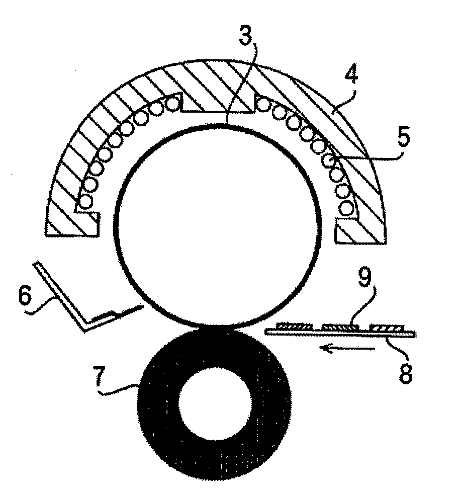
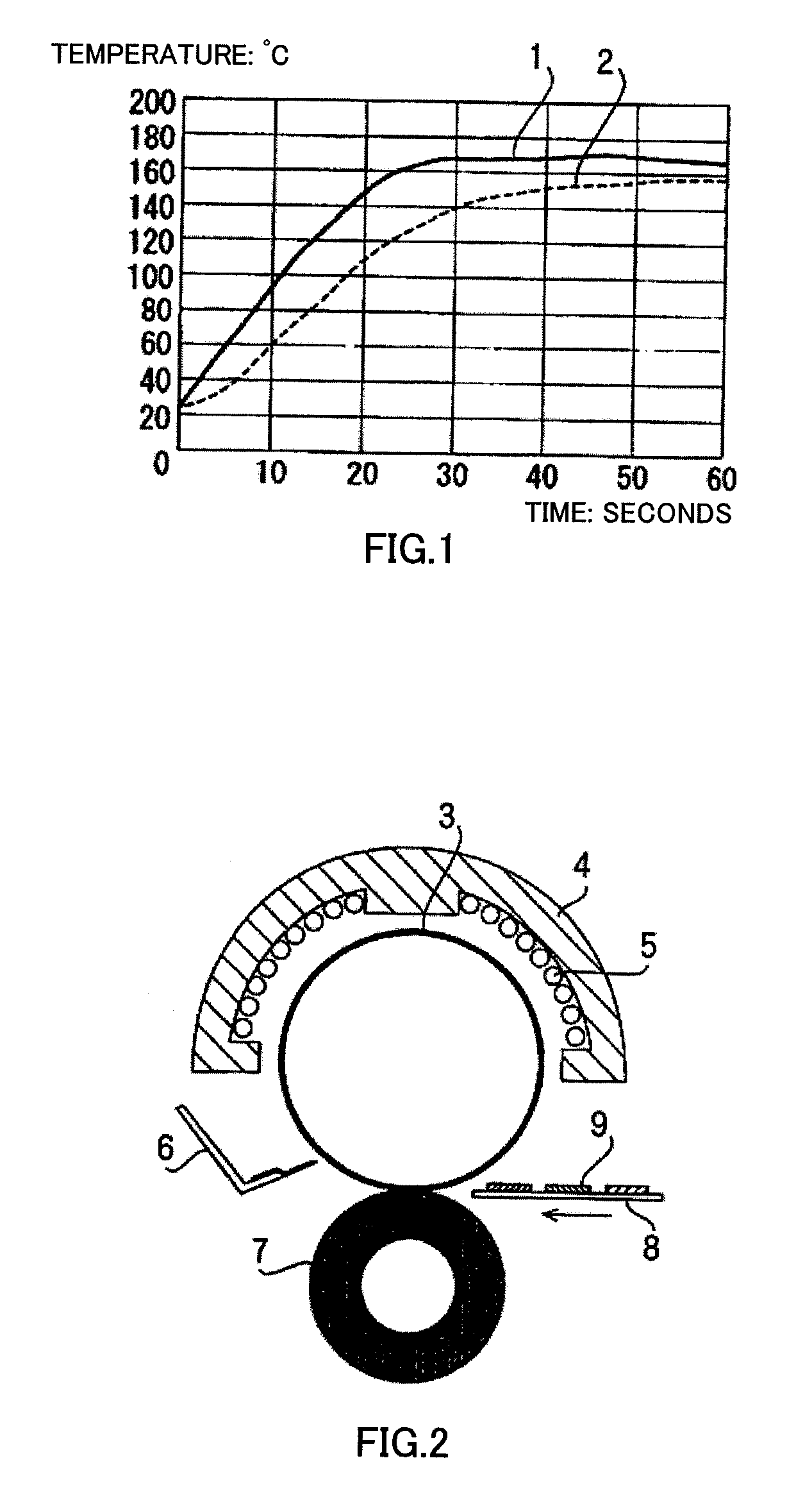
[0059]FIG. 1 is a graph showing time variation of the surface temperature of a fixing roller in a fixing apparatus according to Embodiment 1 of the present invention, and shows time variation of the fixing roller surface temperature when caused to produce heat using a temperature sensitive magnetic metal in an electromagnetic heating type of fixing apparatus.

[0060]When heat production is performed in an electromagnetic heating type of fixing apparatus using a temperature sensitive magnetic metal, heat is generated as Joule heat due to an induction current (eddy current) generated inside the metal by the penetration of magnetic flux, and the electrical resistance of the temperature sensitive magnetic metal as an electrical conductor. Therefore, in order to heat the temperature sensitive magnetic metallic material uniformly, on the one hand it is necessary to make the electrical resistance value uniform, and for this purpose the thickness of the temperature sensitive magnetic metallic...

embodiment 2

[0101]FIG. 7 is a cross-sectional drawing showing the schematic configuration of an image forming apparatus that uses a fixing apparatus according to Embodiment 2 of the present invention.

[0102]As shown in FIG. 7, an electrophotographic photosensitive body (hereinafter referred to as “photosensitive drum”) 21 is mounted in a freely rotatable fashion in an image forming apparatus body 20 of this image forming apparatus. Photosensitive drum 21 is rotated at a predetermined circumferential speed in the direction indicated by the arrow while its surface is uniformly charged to a negative predetermined dark potential V0 by an electrifier 22.

[0103]A laser beam scanner 23 outputs a laser beam 24 modulated in accordance with a time series electrical digital pixel signal of image information input from a host apparatus such as an image reading apparatus or computer (not shown).

[0104]The uniformly charged surface of photosensitive drum 21 is exposed by scanning by laser beam 24. By this means...

embodiment 3

[0152]The general configuration of an image forming apparatus according to Embodiment 3 is the same as that of Embodiment 2 shown in FIG. 7, and therefore a description thereof is omitted here. In this embodiment, only the fixing apparatus configuration differs from that of Embodiment 2.

[0153]FIG. 16 is a cross-sectional drawing showing a fixing apparatus according to Embodiment 3 of the present invention. Fixing apparatus 34a of this embodiment has almost the same configuration as fixing apparatus 34 of Embodiment 2 shown in FIG. 8, but differs from fixing apparatus 34 of Embodiment 2 in that heat-producing roller 50 is replaced by a heat-producing plate 60. Configuration elements in FIG. 16 that have the same reference codes as in FIG. 8 have the same functions as in FIG. 8, and descriptions thereof are omitted here.

[0154]In FIG. 16, heat-producing plate 60 is of temperature sensitive magnetic metal comprising a nickel-iron alloy, and is a 0.3 mm thick arc-shaped plate having the ...


PUM


Abstract

There is provided a fixing apparatus capable of reducing the warm-up time, improving the heating efficiency, and suppressing the temperature increase out of the sheet width by using a magnetic adjuster. In this apparatus, the Currie temperature Tc of the magnetic adjuster material heated by electromagnetic induction is set to 220 degrees C. or below and the fixation setting temperature of a heating member corresponding to the portion where a recording material passes during continuous sheet feed is set lower than a value than the temperature at which the relative magnetic permeability of the magnetic adjuster material begins to decrease. Thus, it is possible to obtain a large difference between the heating portion and the non-heating portion, to surely prevent excessive temperature increase of the portion out of the recording material width, to reduce the warm-up time, and improve the heating efficiency.

Description

TECHNICAL FIELD[0001]The present invention relates to a fixing apparatus used in an image forming apparatus such as an electrophotographic or electrostatographic copier, facsimile machine, or printer, and more particularly to a fixing apparatus that heat-fixes an unfixed image onto a recording material by induction heating and a heating roller used therein, and an image forming apparatus that uses this fixing apparatus.BACKGROUND ART[0002]In recent years, the application of induction heating to a fixing apparatus used in a copier, facsimile machine, printer, or the like, has been much investigated. In an induction heating type of fixing apparatus, an alternating current is applied to an exciting coil, and alternating magnetic flux (magnetic flux whose generation repeatedly ceases) is generated around this exciting coil. An eddy current is generated by permeation of an electrical conductor by the generated alternating magnetic flux, and heat generated in the electrical conductor by t...

Claims


Application Information

Patent Timeline
Patent Type & Authority Applications(United States)
IPC IPC(8): G03G15/20G03G15/14
CPCG03G15/2064G03G2215/2016G03G15/205G03G2215/2032G03G2215/2038G03G2215/2029
Inventor KATAKABE, NOBORUMATSUO, NAOTOMIYANISHI, SATORUHANADA, YASUYUKIIMAI, MASARUTATEMATSU, HIDEKITANI, SHIGEMITSU
Owner PANASONIC CORP
Why Eureka
Try Eureka