Installation Of Offshore Structures

a technology for installing offshore structures and wind turbine generators, which is applied in the direction of machines/engines, drilling pipes, and final product manufacture, etc., can solve the problems of increasing the number of structures to be installed, complex installation, and aggravating difficulties

Active Publication Date: 2009-01-29
IHC IQIP HLDG BV
View PDF99 Cites 64 Cited by
  • Summary
  • Abstract
  • Description
  • Claims
  • Application Information

AI Technical Summary

Benefits of technology

[0050]adjusting the control arrangement such that retraction of the feet is restricted or prevented, whereby the load of the offshore structure is transferred to the offshore support apparatus.

Problems solved by technology

Mounting large structures such as wind turbine generators in offshore locations involves a number of complexities.
Because of the size of the structures they are inherently difficult to transport and there are significant handling issues in achieving a correct alignment of the structure with its offshore support base, jacket or foundation.
These difficulties are aggravated when the sea conditions are less than ideal.
However, it is increasingly required to mount structures such as wind turbines in deeper water where jack-up barges cannot operate.
In the case of a WTG (and similarly for other tall, narrow offshore structures which typically include a shaft, mast or tower which is arranged vertically in use), the WTG is relatively delicate and is also stiff in the longitudinal (vertical) direction.
Usually, the centre of gravity of structures such as WTGs is at a height which is more than twice the width of the base of the structure so that in handling the structure in an upright configuration, instability of the structure is a major concern.

Method used


Image

  • Installation Of Offshore Structures
  • Installation Of Offshore Structures
  • Installation Of Offshore Structures

Examples


Embodiment Construction

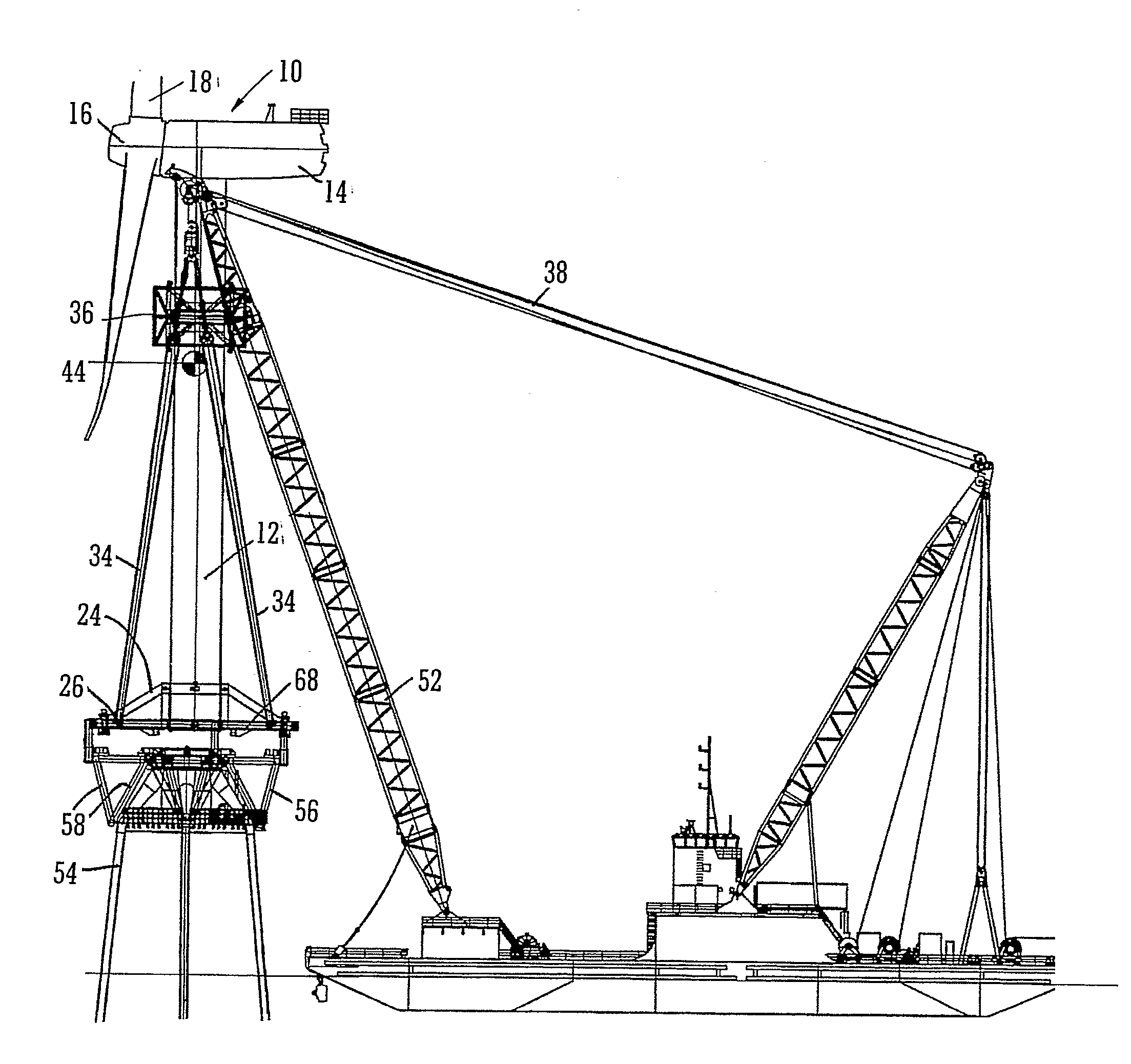
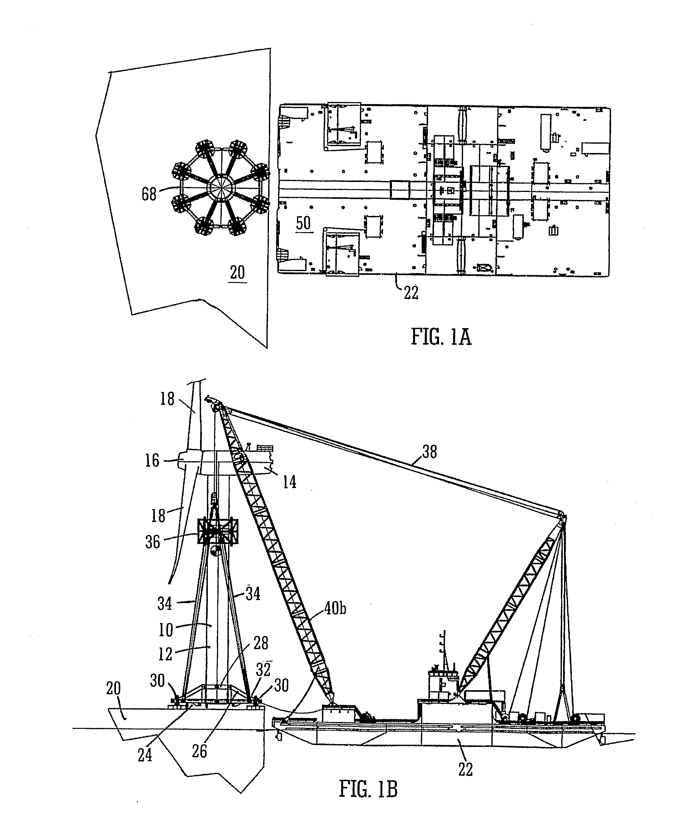
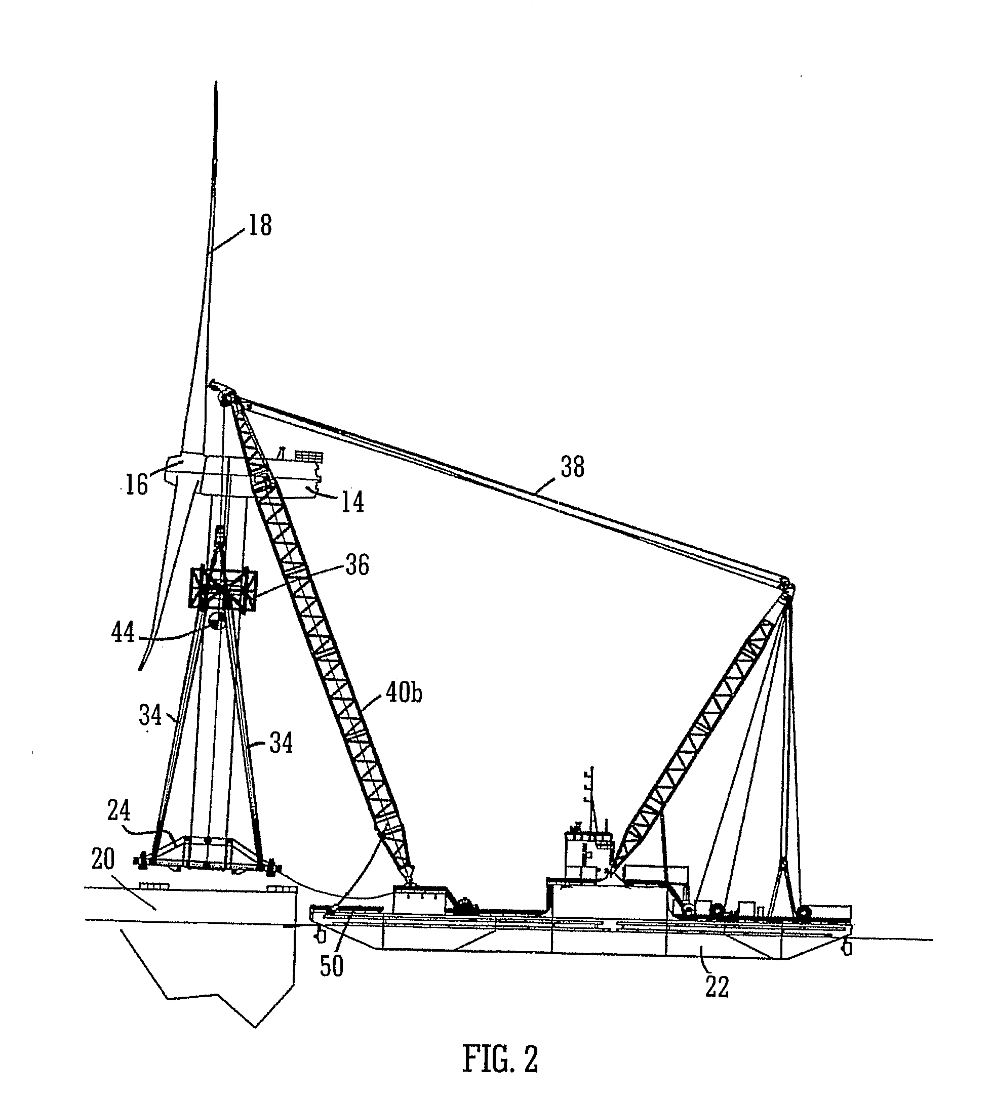
[0064]In the following description, the offshore structure is referred to for convenience as a WTG. It will be appreciated, however that the method, system and apparatus of the invention may be applied to the installation of other offshore structures. Referring now to the drawings, the offshore structure 10 is illustrated as a wind turbine generator which comprises a tower 12, a nacelle 14 housing generator components and a rotor 16 with blades 18. The WTG 10 is constructed on land and assembled at a quayside 20 from where it is collected by a transporting vessel 22. At the quayside 20 the WTG is supported in its upright configuration (as shown in FIG. 1) by a tower supporting apparatus 24 which includes a frame 26 which surrounds the tower 12 and has portions 28 which engage a lower part of the tower 12.

[0065]In operation, typically the frame 26 is assembled at the quayside 20. The frame 26 may conveniently comprise one or more sub-frame portions which are joined together at the qu...


PUM


Abstract

A method and system for transporting an offshore structure such as a wind turbine generator includes a supporting frame in which the offshore structure is assembled on land in an upright configuration. The frame is used for lifting the structure onto a transport vessel, on which it is retained in the upright configuration. At its location of use, the offshore structure is transferred to a pre-prepared foundation. The foundation is provided with a frame which cooperates with the supporting frame. The supporting frame includes a plurality of legs having hydraulically controlled feet. The frame of the foundation includes an equal number of supporting formations on which the feet ultimately rest. The feet are moveable in response to the hydraulic control along a nominally vertical line of action and provide a damping arrangement for the mounting of the offshore structure.

Description

[0001]The present invention relates to methods and apparatus for the installation of offshore structures, and in particular offshore structures such as wind turbine generators. The invention also relates to methods and apparatus for transporting wind turbine generators and similar offshore structures to their location of use offshore.BACKGROUND[0002]Mounting large structures such as wind turbine generators in offshore locations involves a number of complexities. Because of the size of the structures they are inherently difficult to transport and there are significant handling issues in achieving a correct alignment of the structure with its offshore support base, jacket or foundation. These difficulties are aggravated when the sea conditions are less than ideal. In relatively shallow waters it is possible to use so-called jack-up barges which, when the jacks are extended to at least partially support the barge on the seabed, provide a stable platform from which the offshore structur...

Claims


Application Information

Patent Timeline
Patent Type & Authority Applications(United States)
IPC IPC(8): B66C1/42B66C23/52E02B17/00E04H12/34F03D1/00
CPCB63B27/10Y02E10/727B63B2009/067B66C1/108B66C1/42B66C23/185B66C23/52E02B2017/0091E02D27/42F03D1/001F03D1/005F03D11/04F03D11/045F05B2230/6102F05B2240/95B63B35/003B63B75/00E02B17/0004E02D27/425F03D13/10F03D13/22F03D13/25F03D13/40Y02E10/72Y02P70/50E02B17/00E04H12/34F03D1/00
Inventor BINGHAM, MARTINGRINSTED, TIMOTHY WILLIAMWATCHORN, MICHAEL JOHN
Owner IHC IQIP HLDG BV
Why Eureka
Try Eureka