Non-Contacting Thermal Rotary Joint

a technology of thermal rotary joints and non-contact heat, which is applied in the direction of manipulators, manufacturing tools, light and heating equipment, etc., can solve the problems of difficult to remove the heat from the turntable, electronic components could be damaged, and electrical power consumed by electronic components and generate hea

Active Publication Date: 2009-02-05
HARRIS CORP
View PDF13 Cites 45 Cited by
  • Summary
  • Abstract
  • Description
  • Claims
  • Application Information

AI Technical Summary

Benefits of technology

[0012]In the one embodiment of the invention, the first substrate and the second substrate are comprised of a thermally conductive material. The thermally conductive material selected is aluminum. Aluminum is also highly desirable since the first fin ring and the second fin ring can be etched or machined directly into the first side surfaces of the first substrate and second substrate, respectively. The material selected is anodized to further improve the thermal radiation between the two substrates.

Problems solved by technology

The electronic components consume electrical power and generate heat which must be removed from the turntable or else the electronic components could be damaged.
Since the turntable must rotate to align the antenna with a communications satellite, it can be difficult to remove the heat from the turntable.
Drawbacks to the use of liquid rotary unions for this purpose are that they have a finite life, induce friction, and stiction and risk potential leaks which are particularly undesirable for satellite antennas such as small, precision antenna tracking positioners.
Convection and radiation fins could be used but are limited in their effectiveness and efficiency in dissipating heat.
The aforementioned thermoelectric devices and heat pipes have been considered but are not capable of transporting heat across a rotating joint.
Moreover, thermoelectric devices can be used with a slip ring but at an increased size, weight, and cost.

Method used


Image

  • Non-Contacting Thermal Rotary Joint
  • Non-Contacting Thermal Rotary Joint
  • Non-Contacting Thermal Rotary Joint

Examples


Embodiment Construction

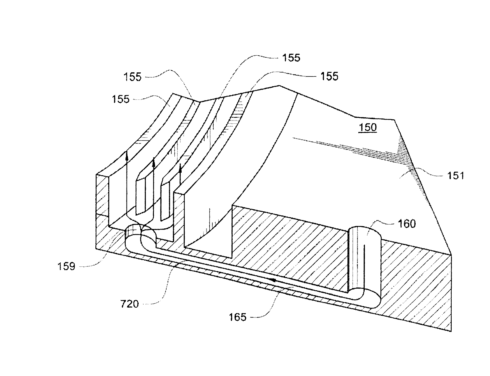
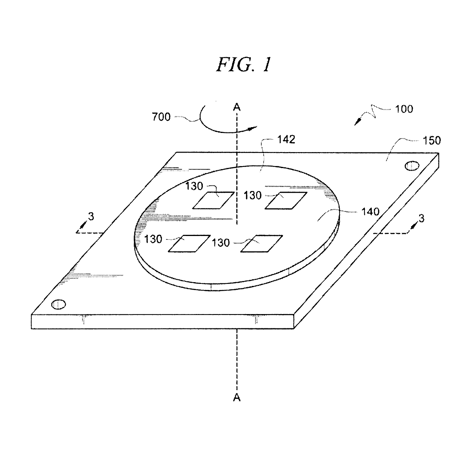
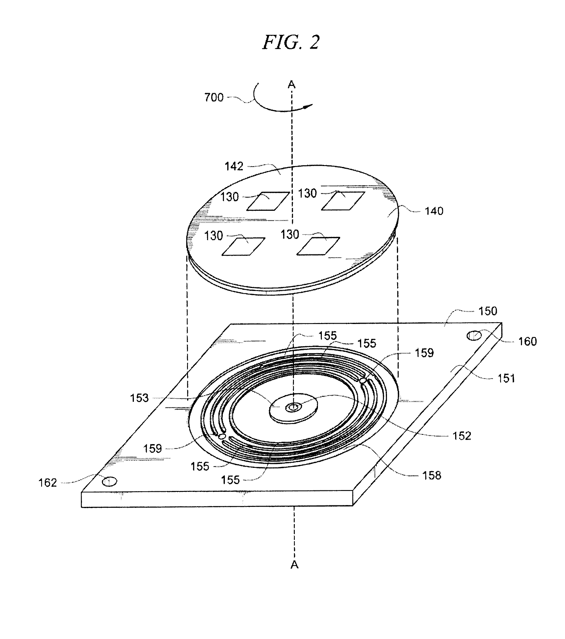
[0032]Referring now to FIG. 1, shown is perspective view of an apparatus 100 comprising a first substrate 140 rotatably mounted to a second substrate 150. The first substrate 140 is rotatable relative to the second substrate 150 about a rotational axis A-A. In the embodiment of the invention shown in FIG. 1, the first substrate 140 is rotatable relative to the second substrate 150 about the rotational axis A-A in the direction of arrow 700. In another embodiment of the invention, the first substrate 140 is rotatable relative to the second substrate 150 about the rotational axis A-A in the direction opposite arrow 700.

[0033]The apparatus 100 is typically used in an application involving electronic equipment (not shown). In this regard, a plurality of thermal energy generating devices 130 could be disposed on a first or upper side surface 142 of the first substrate 140. The thermal energy generating devices 130 are devices including but not limited to electronic components, motors, or...


PUM


Abstract

An apparatus (100) for transferring heat from a first substrate (140) rotatably mounted to a second substrate (150). The apparatus (100) is comprised of at least a first fin ring (145) disposed concentrically on a first side surface (141) of the first substrate (140). A plurality of heat generating devices (130) is disposed on a second side surface (142) of the first substrate (140). There is at least a second fin ring (155) disposed concentrically on a first side surface (151) of the second substrate (150). The first fin ring (145) interleaves with the second fin ring (155) while allowing the first substrate (140) to rotate unobstructed relative to the second substrate (150). The second substrate (150) has at least a first port (160) for introducing moving air into a gap (G) defined between the first fin ring (145) and the second fin ring (155) for improving heat convection there between.

Description

BACKGROUND OF THE INVENTION[0001]1. Statement of the Technical Field[0002]The invention relates to a non-contacting thermal rotary joint. More particularly, this invention relates to a non-contacting thermal rotary joint for transferring heat from heat generating devices disposed on a first substrate to a second substrate wherein the first substrate is rotatably mounted to the second substrate.[0003]2. Background of the Invention[0004]There are many applications where it is desirable or essential to transfer heat from a first substrate to a second substrate. The first substrate could have heat generating devices disposed thereon which generate heat which must be removed. It is desirable to transfer the heat to the second substrate which is disposed adjacent to the first substrate. The second substrate could be further thermally coupled to a heat sink for removing the heat from the second substrate.[0005]In such applications, pin heat exchangers, liquid cooling, thermoelectric device...

Claims


Application Information

Patent Timeline
Patent Type & Authority Applications(United States)
IPC IPC(8): F28D15/00
CPCB25J19/0054F28D15/00F28F2013/005F28F5/00F28D2021/0029
Inventor ZIMMERMAN, KURTMEEHAN, ROBERT F.RUST, JOHN
Owner HARRIS CORP
Why Eureka
Try Eureka