Powder classifying device

a classifying device and powder technology, applied in the direction of gas current separation, solid separation, chemistry apparatus and processes, etc., can solve the problems of inability to achieve satisfactory results in terms of classification accuracy and operability (or particle size controllability), complicated structure of the device, etc., to achieve easy particle size control and maintenance, high degree of accuracy, and high efficiency

Active Publication Date: 2009-02-05
NISSHIN SEIFUN GRP INC
View PDF23 Cites 14 Cited by
  • Summary
  • Abstract
  • Description
  • Claims
  • Application Information

AI Technical Summary

Benefits of technology

[0031]The present invention is highly effective in realizing a powder classifying device that is capable of classifying particulates having sizes equal to or smaller than about several micrometers and sub-micron sized particulates with a high degree of accuracy and offers easy particle size control and maintenance.
[0032]More specifically, the present invention is highly effective in realizing a powder classifying device which has such a structure that a plurality of air nozzles are arranged on the outer peripheral wall of the disc-like cavity along the tangential direction of the outer peripheral wall and blow compressed air into the disc-like cavity, and which is advantageous in producing powder having sizes equal to or smaller than about several micrometers or on the order of sub-microns.
[0033]The powder classifying device according to the third aspect of the present invention, i.e., the powder classifying device in which the centrifugal chamber is vertically arranged is advantageous in that this powder classifying device requires a considerably reduced area for its installation compared with the case of a powder classifying device in which a centrifugal chamber of the same processing ability is horizontally arranged. The powder classifying device according to the fourth aspect of the present invention, i.e., the two-stage device having two powder classifying devices of the same size placed one on top of another is also effective in reducing the installation area.

Problems solved by technology

Therefore, the structure (manufacturing process) of the devices is complicated.
When powder having high adhesion properties or particulates on the order of microns (equal to or smaller than about several micrometers) or sub-microns are classified, a satisfactory result cannot be obtained in terms of classification accuracy and operability (or particle size controllability).

Method used


Image

  • Powder classifying device
  • Powder classifying device
  • Powder classifying device

Examples


example

[0121]A specific example is described below.

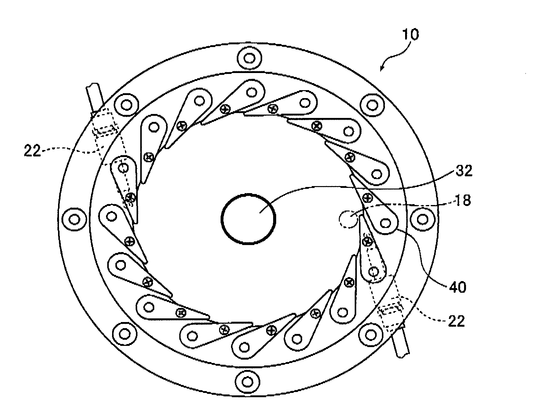
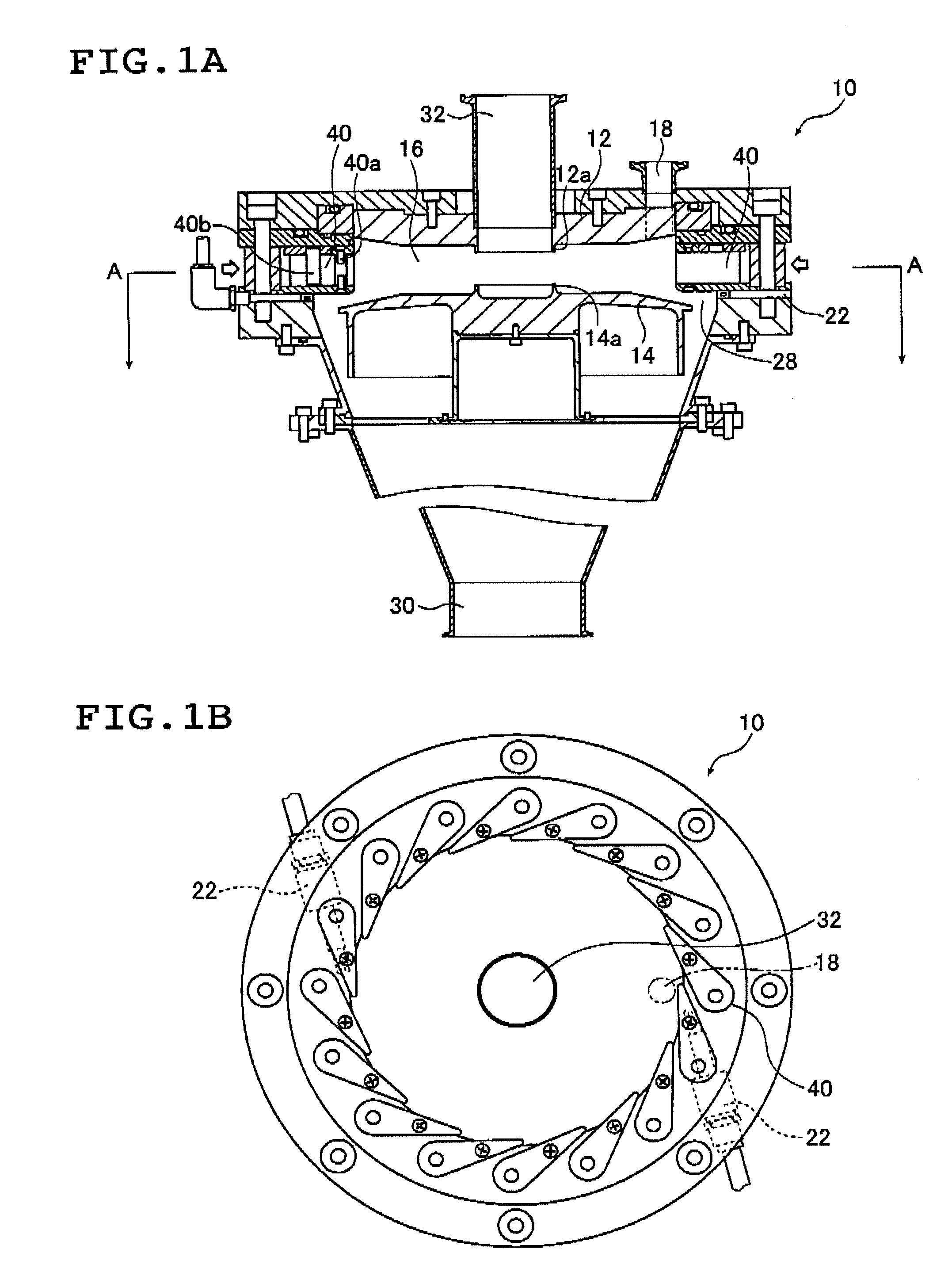
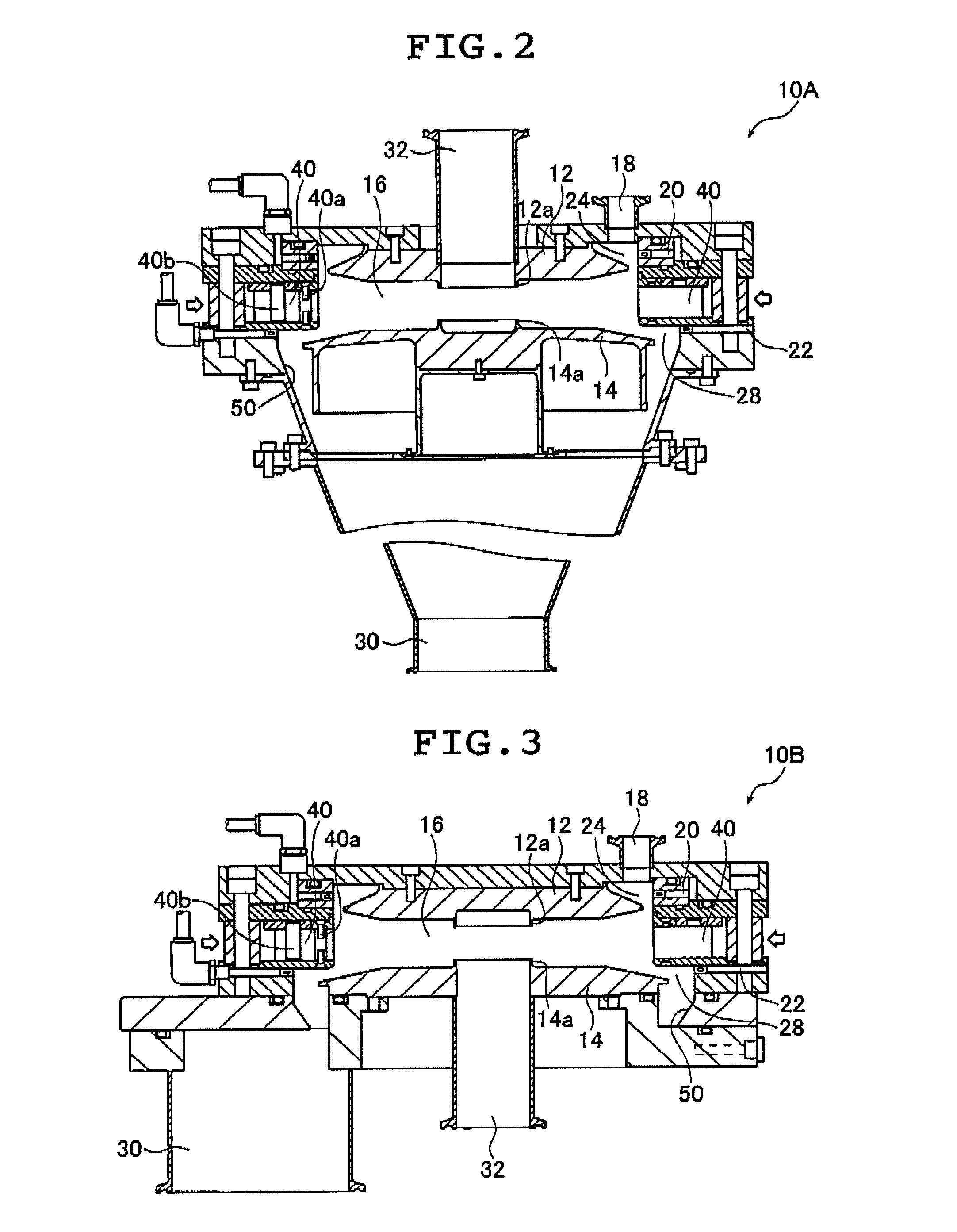
[0122]The powder classifying device 10A having the configuration shown in FIG. 2 was used in Example 1, and a powder classifying device obtained by removing the two types of nozzles including the first and second discharge nozzles 20 and 22 and the ring-like edges 12a and 14a provided on the upper side and the lower side of the centrifugal chamber 16 from the powder classifying device 10A having the configuration shown in FIG. 2 was used as a conventional powder classifying device in Comparative Example 1.

[0123]The inclination angle of the guide vanes 40 from the tangential direction of the outer peripheral wall toward the center of the centrifugal chamber 16 within the powder classifying device was set to 10 degrees in both Example 1 and Comparative Example 1.

[0124]In Example 1, the pressure of air discharged from the upper and lower discharge nozzles 20 and 22 was set to 0.5 MPa and the flow rate of air discharged per nozzle was set to 2...


PUM

PropertyMeasurementUnit
inclination angleaaaaaaaaaa
flow rateaaaaaaaaaa

Abstract

The powder classifying device classifies powder having a particle size distribution and collects the classified powder. The device includes a disc-like cavity to which the powder is supplied and where the supplied powder is classified, a powder supply port for supplying the powder to the cavity, guide vanes arranged so as to extend from an outer periphery of the cavity in an inner direction at a predetermined angle, a discharge unit for air streams including fine particles discharged from the cavity, a collection unit for coarse particles discharged from the cavity and air nozzles arranged below the guide vanes on an outer peripheral wall of the cavity along a tangential direction of the outer peripheral wall and blow compressed air into an inside of the cavity.

Description

[0001]The entire contents of all documents cited in this specification are incorporated herein by reference.BACKGROUND OF THE INVENTION[0002]The present invention relates to a powder classifying device that classifies powder having a particle size distribution according to one or more desired particle sizes (classification points), and more particularly, to a powder classifying device that can classify powder preferably having sizes equal to or smaller than about several micrometers with a high degree of accuracy making use of a balance between centrifugal force given to the powder by circulating air streams and drag.[0003]For example, a powder classifier as disclosed in JP 06-83818 B is known in which a powder input port is provided in the center of the upper surface, a powder path is formed along the conical surface spreading from the vertex of a cone provided right below the powder input port, the lower end of the powder path is located in substantially the center of a plurality ...

Claims


Application Information

Patent Timeline
Patent Type & Authority Applications(United States)
IPC IPC(8): B07B4/00
CPCB07B4/02B07B11/04B07B7/086B07B11/02B07B11/00
Inventor TAKETOMI, KENJIKOZAWA, KAZUMIKYUGO, MASARU
Owner NISSHIN SEIFUN GRP INC
Why Eureka
Try Eureka