
Overfill protection device (OPD)

Active Publication Date: 2009-02-05
SCG (THAILAND) CO LTD
View PDF15 Cites 5 Cited by
  • Summary
  • Abstract
  • Description
  • Claims
  • Application Information

AI Technical Summary

Benefits of technology

[0006]Therefore, it is an objective of the present invention to solve the above-mentioned problems and to provide an overfill protection device which is safe to use and operate regardless of the person who handles it and how it is handled.
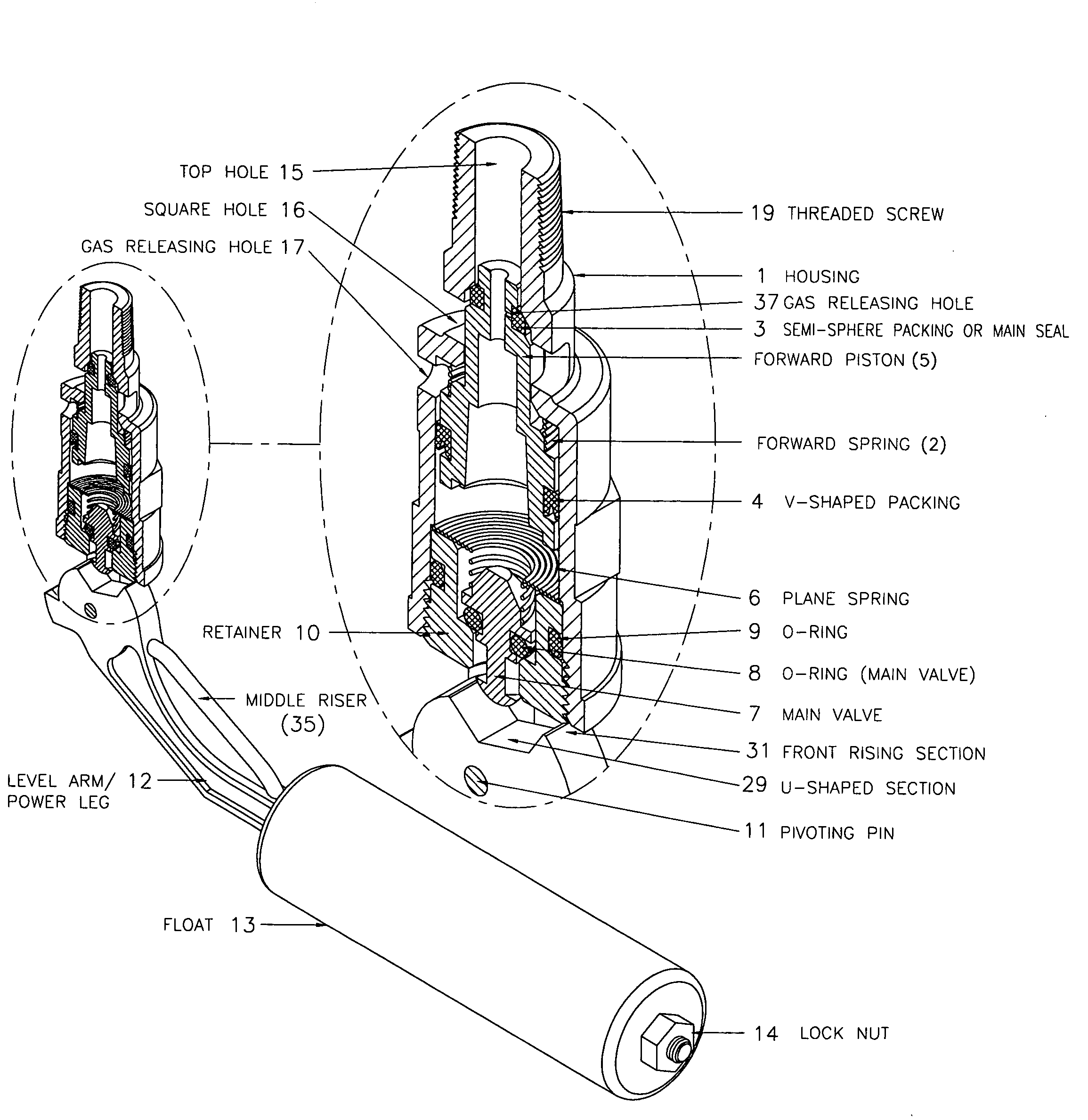
[0008]Generally, propane and butane which is in liquid phase will evaporate when the gas is heating up and the pressure rises. With the 20 percent space at the top of the cylinder, the liquid phase is allowed to expand to the vapor phase, so the cylinder is not in the threat of expanding too much until it explodes. As a result, the danger of the gas cylinder explosion due to the overfilling can be avoided. The OPD is activated at the designated level so that the overfilling is prohibited. Normally, the designated level is 80 percent in order to leave enough room at the top of the cylinder for the gas to expand. Without this device, the careless filler may overshoot the filling process, thus the tank will be overfilled. When this happens, the liquid gas is at its maximum level. There is no room for the liquid gas to expand. Once the cylinder is put under the sun or near the stove, the heat will cause the gas to expand. Without the 20 percent space at the top, the liquid will act as a hydraulic tool when it expands. The pressure that is exerted to the shell of the cylinder is enormous. If this pressure happens to be greater than the determined pressure of the cylinder, the breakage of the cylinder is unavoidable. However, if we have this OPD device, even if the operator forgets to shut off the pump or close the valve when the filling reaches the 80 percent level, it will prevent the overfilling from happening and the 20 percent space at the top of the cylinder can always be obtained. So if the cylinder is heating up, the chance of the cylinder to explode due to the gas expansion with 20 percent leverage at the top is not possible. Therefore, the safety of the cylinder can be enhanced.

Problems solved by technology

Without this device, the careless filler may overshoot the filling process, thus the tank will be overfilled.
The pressure that is exerted to the shell of the cylinder is enormous.
If this pressure happens to be greater than the determined pressure of the cylinder, the breakage of the cylinder is unavoidable.
So if the cylinder is heating up, the chance of the cylinder to explode due to the gas expansion with 20 percent leverage at the top is not possible.

Method used


Image

  • Overfill protection device (OPD)
  • Overfill protection device (OPD)
  • Overfill protection device (OPD)

Examples


Embodiment Construction

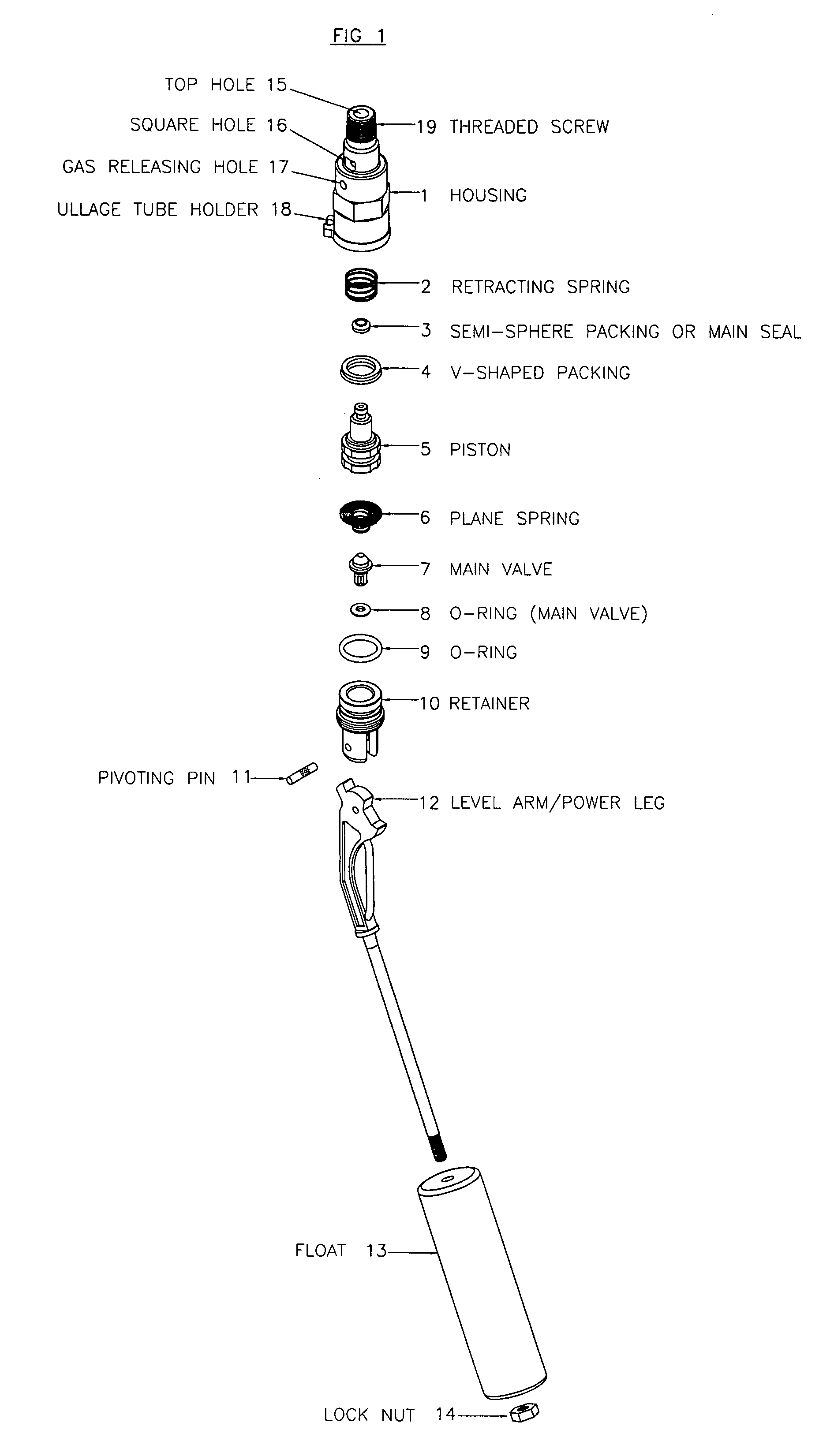
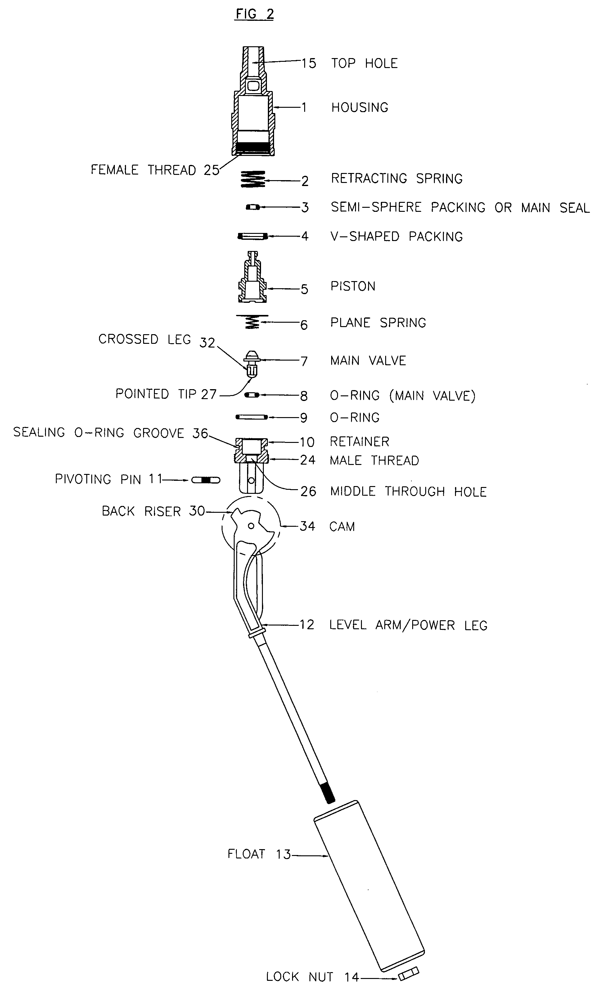
[0017]The assembly of the “Overfill Protection Device” is as illustrated in the exploded drawings of FIG. 1 and FIG. 2. It contains the housing (1) which has 3 unique holes and a holder. The top hole (15) which is in the centre of the housing (1) has a circular shape. It allows gas to flow in and out of the device. On the outside of the housing (1), there is a threaded screw (19) which is to be screwed onto the valve body as can be seen in FIG. 8. The second hole is the square hole (16) which protrudes across the lower part of the circular hollow hole in the middle. This square hole (16) allows the gas to flow through from the center top hole (15) into the tank. The other hole is the gas releasing hole (17) which allows the extra gas to release into the tank so that the breakage of the housing does not occur in case there is excessive pressure acting inside the housing (1). The holder (18) is used to hold the ullage tube (39) which measures the 80 percent level of the liquid filled....


PUM


Abstract

An overfill protection device includes a piston (5) comprising a main seal or semi-sphere packing (3) on its tip and a V-shaped packing (4) on its side, a retracting spring (2) for pushing the piston back to its original position, a main valve (7) with an o-ring that drops into the inner hole of the retainer (10) to block off the gas flow, a level arm consisting of a rising faced section (28) and a U-shaped section (29), whereby no gas will be allowed to flow through the overfill protection device when the gas reaches the predetermined 80 percent level.

Description

FIELD OF INVENTION[0001]Mechanical engineering related to overfill protection deviceBACKGROUND OF THE INVENTION[0002]The present invention relates to an overfill protection device, more particularly to an overfill protection device used for a fluid container to prevent overfilling of the container or gas cylinder, with an ullage tube to determine the 80 percent level of the liquid filled in the container or gas cylinder.DESCRIPTION OF THE PRIOR ART[0003]Devices which use gas, such as liquefied petroleum gas (LPG), liquefied natural gas (LNG), compressed natural gas (CNG), etc., need to be refilled when a gas storage tank of the device is empty.[0004]To prevent the explosion which possibly occurs due to the overfilling of gas when the gas is filled in the storage tank, it is required to provide a safety valve which, in the case of charging the gas with a certain level of a gas pressure, automatically operates by the gas pressure in the gas storage tank and is then operated to externa...

Claims


Application Information

Patent Timeline
IPC IPC(8): F16K3/18
CPCF17C2250/0413F16K31/26Y10T137/7361Y10T137/7371Y10T137/7439
Inventor KIDPRASERT, JAKAPHAN
Owner SCG (THAILAND) CO LTD
Learn More