Optically compensated bend mode liquid crystal display devices

a liquid crystal display and bend mode technology, applied in static indicating devices, instruments, non-linear optics, etc., can solve the problems of limiting application fields, complex process, and the need for photolithography process using a half-tone mask

Inactive Publication Date: 2009-02-05
IND TECH RES INST
View PDF6 Cites 14 Cited by
  • Summary
  • Abstract
  • Description
  • Claims
  • Application Information

AI Technical Summary

Problems solved by technology

Conventional LCDs have a relatively narrower viewing angle, thus limiting application fields.
However, a complex process, such as a photolithography process using a half-tone mask, is required to form the bumps or protrusions on the substrate.
Because l

Method used


Image

  • Optically compensated bend mode liquid crystal display devices
  • Optically compensated bend mode liquid crystal display devices
  • Optically compensated bend mode liquid crystal display devices

Examples


Embodiment Construction

[0032]The following description is of the best-contemplated mode of carrying out the invention. This description is made for the purpose of illustrating the general principles of the invention and should not be taken in a limiting sense. The scope of the invention is best determined by reference to the appended claims.

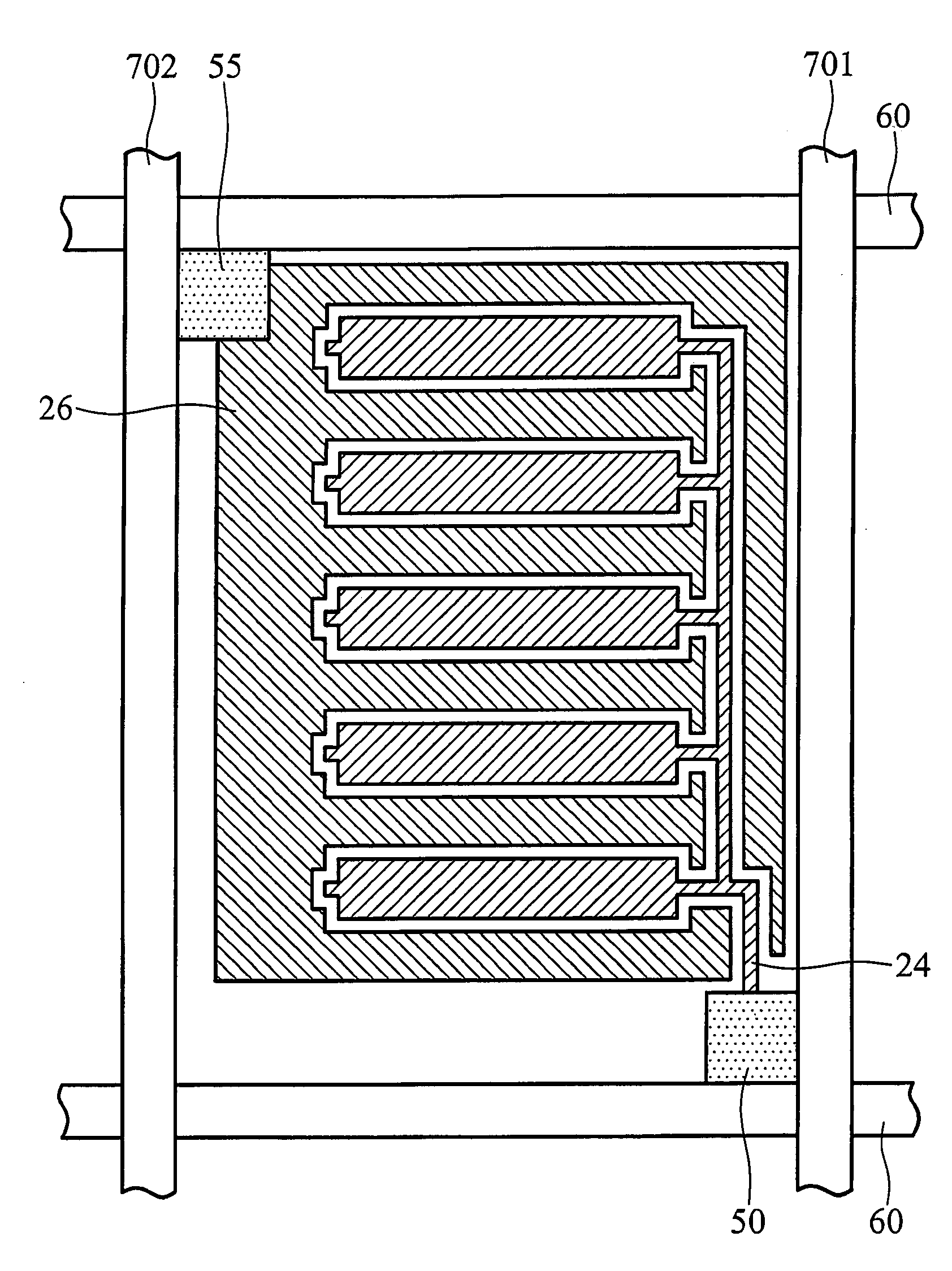
[0033]FIG. 3a and FIG. 3b are top views showing a single pixel unit of an OCB mode liquid crystal display device. FIG. 4a is a cross section taken along I-I′ line of FIG. 3a.

[0034]Referring to FIG. 4a, an OCB mode liquid crystal display device 10 comprises a first substrate 20, a second substrate 30 and a liquid crystal layer 40 interposed therebetween. The first substrate 20 and the second substrate 30 are disposed oppositely to each other. The first substrate 20 is a so-called active matrix substrate having a thin film transistor array and the second substrate 30 is color filter substrate having a color filter layer 34 and a black matrix 32. The OCB mode liquid crys...


PUM


Abstract

An OCB mode liquid crystal display device is provided. The OCB mode liquid crystal display device comprises a first substrate, a second substrate and a liquid crystal layer interposed therebetween. The first substrate and the second substrate are disposed oppositely to each other. The device further comprises a first pixel electrode disposed on the first substrate, a second pixel electrode disposed on the first substrate and spaced apart from the first pixel electrode by a distance. The first pixel electrode and second pixel electrode are alternately arranged. The device further comprises a first alignment layer disposed on the first substrate to cover the first pixel electrode and the second pixel electrode, a common electrode disposed on the second substrate, and a second alignment layer disposed on the second substrate covering the common electrode.

Description

BACKGROUND OF THE INVENTION[0001]1. Field of the Invention[0002]The present invention relates to liquid crystal display (LCD) devices and methods for manufacturing the same, and in particular relates to optically compensated bend (OCB) mode liquid crystal display devices and methods for manufacturing the same.[0003]2. Description of the Related Art[0004]Liquid crystal display (LCD) devices have many advantages such as a smaller volume, lighter weight and lower power consumption. Due to features of LCDs such as a lighter weight, thinner profile, and increased portability, LCDs are applicable in a variety of electronic and communication devices including notebook computers, personal digital assistants (PDA), mobile phones and the like.[0005]Conventional LCDs have a relatively narrower viewing angle, thus limiting application fields. Multi-domain vertical alignment (MVA) LCDs have been proposed to increase viewing angle, in which bumps or protrusions are disposed on the substrate of an...

Claims


Application Information

Patent Timeline
IPC IPC(8): G02F1/1333G02F1/13G02F1/1337
CPCG02F1/134309G02F1/13624G02F2201/124G02F2201/123G02F1/1395
Inventor LEE, KUO-CHANGLO, KUO-LUNG
Owner IND TECH RES INST
Why Eureka
Try Eureka