Design Panel

a design panel and panel body technology, applied in the field of design panels, can solve the problems of insufficiently obtaining electronic equipments with improved design, difficult to see information displayed on the display surface of display devices, and dark display surfaces, etc., to achieve improved improve the design of electronic equipment, and high smoothness

Inactive Publication Date: 2009-02-05
NISSHA PRINTING COMPANY
View PDF5 Cites 23 Cited by
  • Summary
  • Abstract
  • Description
  • Claims
  • Application Information

AI Technical Summary

Benefits of technology

[0035]In accordance with the present invention has the black-colored section which is to be arranged at a position corresponding to the frame portion surrounding the opening of the casing for an electronic equipment supporting the design panel, and the concealing section which is to be arranged at a position corresponding to the opening, when the display device is in the standby state, the display surface of the display device and the frame portion look like one unit when viewed through the design panel, that is, they cannot be visually distinguished from each other. Therefore, a user (an observer) cannot visually recognize the display device from the exterior of the design panel, and the display panel looks like a black window to the user. That is, the design panel can conceal the presence of the display device when the display device is in the standby state because the design panel looks like a solid black window. On the other hand, when information is displayed on the display surface of the display device, the display device becomes visible from the exterior of the casing for the electronic equipment, and therefore the user feels that visual images pop up on the display surface of the display device, which is effective from the viewpoint of improving the design of the electronic equipment.
[0036]Further, when the polarizing film of the concealing section is arranged so as to have the absorption axis that is the same as that of the polarizing plate of the liquid crystal display device, it is possible to pass a larger amount of light emitted from the light source of the display device through the design panel when information is displayed on the display surface of the display device, thereby improving the design of the electronic equipment.
[0037]Further, when the polarizing film is provided so as to be adjacent to the inside surface of the transparent support substrate, the transparent support substrate is located on the outermost side of the design panel, and therefore the design panel can have a surface having high smoothness and scratch resistance. In addition, it is possible to prevent the formation of a step resulting from the polarizing film and therefore to eliminate the fear of separation of the polarizing film from the design panel.
[0038]Further, when the black-colored section is provided on a closer side to an attachment side of the casing with respect to the polarizing film, the black-colored section is more likely to be similar in color to the display device in the standby state having the black display surface. Therefore, it is difficult to discern a boundary between the display device and the design panel, thereby improving the design of the electronic equipment.
[0039]Further, when the black-colored section is printed on the ¼ wavelength phase difference film, it is possible to reduce the thickness of the black-colored section and therefore to reduce the thickness of the entire design panel.
[0040]Further, when the black-colored section comprises the black double-sided pressure-sensitive adhesive tape, it is possible to eliminate the necessity to separately provide a step of forming a black-colored section and therefore to reduce costs and improve productivity.

Problems solved by technology

According to the first possible method, it is possible to make the display surface of the display device indistinguishable from the frame portion when the display device is in a standby state (that is, when information is not displayed on the display surface), but due to an extremely low transmittance of the smoked panel, there is an issue that the display surface gets dark and therefore hard to see when information is displayed on the display surface of the display device.
However, in this case, it is obvious that the display surface of the display device can be easily distinguished from the frame portion when the display surface is viewed from the front thereof, and therefore the above object of obtaining electronic equipments having an improved design cannot be fully achieved.
Further, the transparent panel having such a special film attached thereto has a lower transmittance than the transparent panel used alone, which causes an issue that the display surface of the display device gets dark and therefore hard to see when information is displayed on the display surface.
Furthermore, as described above, since visual images on the display surface are hard to see from angles other than the front of the display surface, a user needs to always face the front of the display surface of the display device to see the display surface, which makes it hard to use the electronic equipment.

Method used


Image

  • Design Panel
  • Design Panel
  • Design Panel

Examples


first embodiment

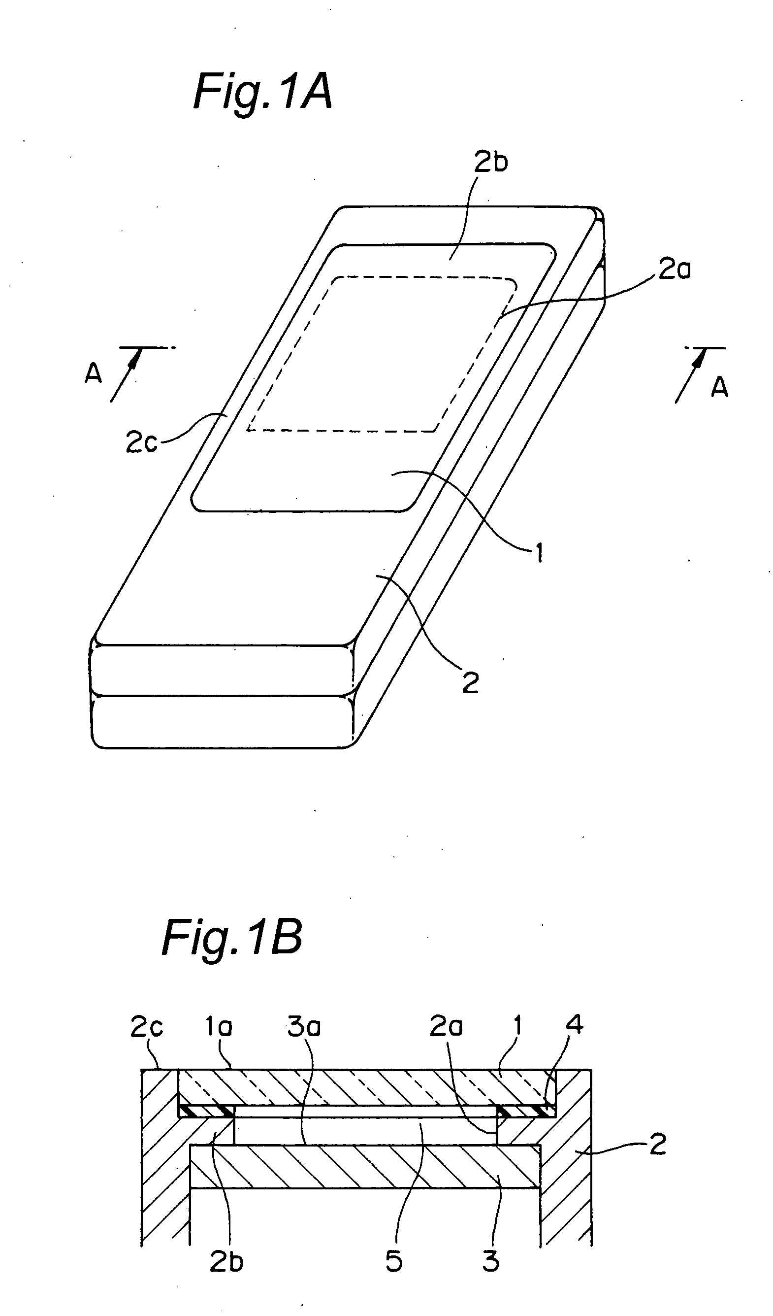
[0062]FIG. 1A is a perspective view which shows a basic structure of a mobile phone using a design panel 1 according to a first embodiment of the present invention, and FIG. 1B is a schematic view which shows the cross section A-A of the mobile phone shown in FIG. 1A.

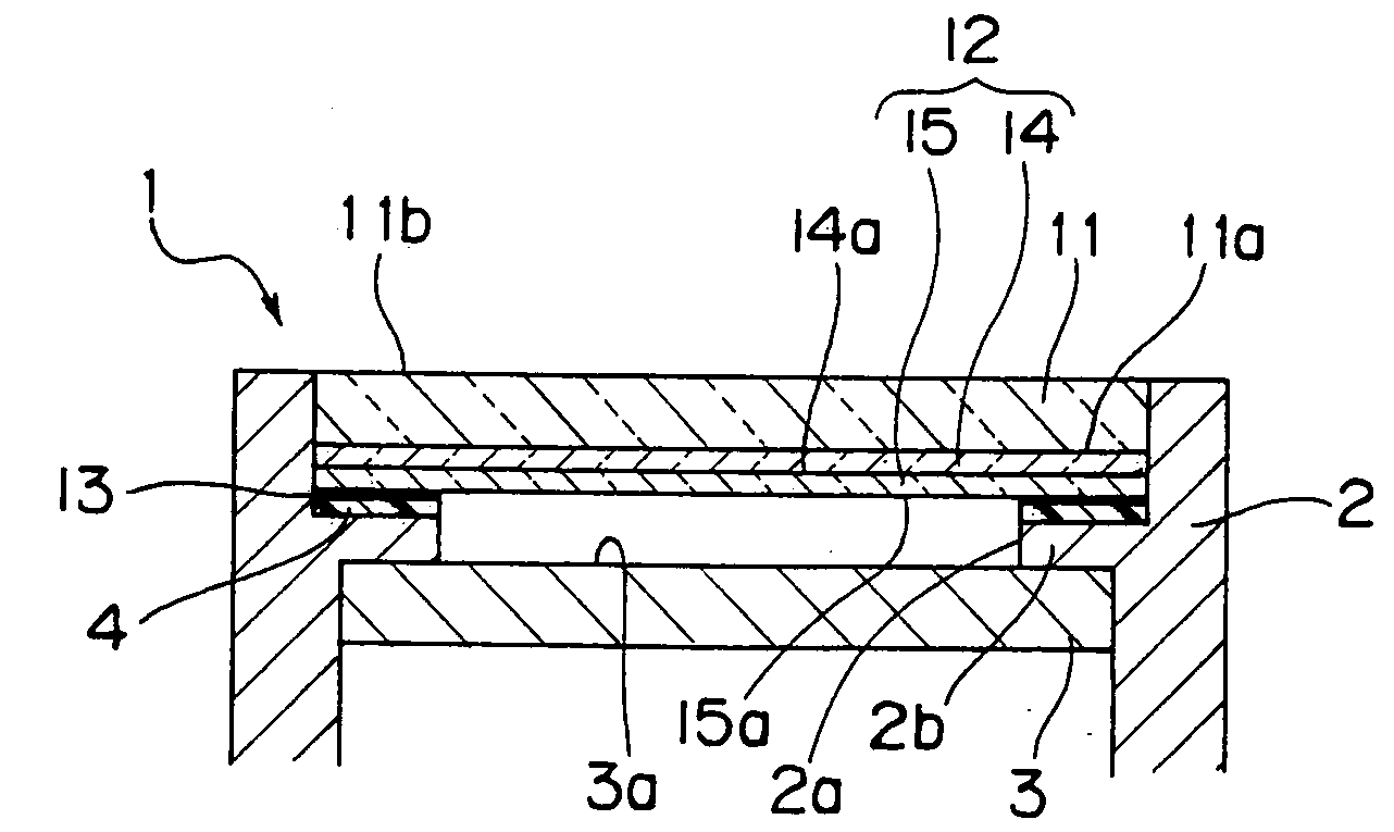
[0063]The design panel 1 (which is a diagonally shaded area in FIG. 1A) is externally attached to a casing 2 made of metal such as aluminum or resin with a double-sided pressure-sensitive adhesive tape 4 to cover an opening 2a partially formed in the surface of the casing 2, and is supported by a frame portion 2b surrounding the opening 2a. The opening 2a of the casing 2 is formed so that a display surface 3a of a display device 3 provided in the casing 2 is visible from the exterior of the casing 2. The design panel 1 has a larger area than the opening 2a, and is arranged so as to be opposed to the display surface 3a of the display device 3 with an air layer 4 being interposed therebetween. An upper (outer) surface 2c ...

first working example

[0082]A design panel according to First Working Example had a structure shown in FIG. 3B. A transparent support substrate was prepared by dip-coating the both surfaces of a methacrylate (PMMA) plate having a thickness of 1 mm with an epoxyacrylate-based polyfunctional acrylate UV curable resin so that the thickness of the resin was 5 μm. A polarizing film had optical properties such as a degree of polarization of 99.5% and a single piece transmittance of 43%, and was attached to the entire lower surface of the transparent support substrate with a transparent acrylic-based pressure-sensitive adhesive so as to have an absorption axis that was the same as the absorption axis (45°) of an upper polarizing plate of a display device. A ¼ wavelength phase difference film was attached to the entire lower surface of the polarizing film with a transparent acrylic-based pressure-sensitive adhesive so that the absorption axis thereof formed 45° with the absorption axis of the polarizing film. A ...

second working example

[0083]A design panel according to Second Working Example had a structure shown in FIG. 6. A transparent support substrate was prepared by dip-coating the both surfaces of a polycarbonate (PC) plate having a thickness of 0.7 mm with an urethaneacrylate-based polyfunctional acrylate UV curable resin so that the thickness of the resin was 3 μm. A polarizing film had optical properties such as a degree of polarization of 99.5% and a single piece transmittance of 43%, and was attached to the entire lower surface of the transparent support substrate with a transparent acrylic-based pressure-sensitive adhesive so as to have an absorption axis that was the same as the absorption axis (135°) of an upper polarizing plate of a display device. A black-colored section was formed by printing the shape of a frame portion of the display device with black ink by gravure printing on an optically isotropic polycarbonate film having a thickness of 100 μm and attaching the film to the entire lower surfa...


PUM

PropertyMeasurementUnit
wavelengthaaaaaaaaaa

Abstract

A design panel attached to a casing for an electronic equipment, which is constructed so that a display device whose display surface goes black at standby is placeable inside the casing, and which is formed with an opening that makes the display surface visible, the design panel being attached to the casing so as to cover the opening, the design panel including, a transparent support substrate having a larger area than the opening, a polarizing film provided outside or inside the transparent support substrate, a ¼ wavelength phase difference film provided on a closer side to an attachment side of the casing with respect to the polarizing film, and a black colored section provided on the closer side to the attachment side of the casing with respect to the transparent support substrate, for blacking a portion which is able to be in contact with the casing, wherein the display device is made visible from the outside at information display, whereas the display device is covered so as to be made invisible from the outside at standby.

Description

TECHNICAL FIELD[0001]The present invention relates to a design panel to be used for electronic equipment equipped with a display device, such as mobile phones and smart phones.BACKGROUND ART[0002]A conventional electronic equipment incorporating a display device therein has an opening to make a display surface of the display device visible from its exterior, and the opening is entirely covered with a transparent panel, such as a glass panel or a plastic panel, externally attached to the electronic equipment.DISCLOSURE OF THE INVENTIONIssue to be Solved by the Invention[0003]The conventional electronic equipment having such a structure described above has a transparent panel, and therefore when viewed through the transparent panel, the display surface of the display device can be easily distinguished from a frame portion surrounding the opening formed in a casing for the electronic equipment supporting the transparent panel. In recent years, a user demand for the electronic equipment...

Claims


Application Information

Patent Timeline
Patent Type & Authority Applications(United States)
IPC IPC(8): G02F1/1335
CPCG02B27/286G02F1/133308G02F2203/64G02F2001/133638G02F2001/133388G02F1/133388G02F1/133638G02F1/13G02F1/1333G02F1/1335
Inventor NISHIKAWA, KAZUHIROASAKURA, TAKESHIKAI, YOSHIHIRO
Owner NISSHA PRINTING COMPANY
Why Eureka
Try Eureka