

Transflective liquid crystal displays
a liquid crystal display and reflector technology, applied in static indicating devices, instruments, non-linear optics, etc., can solve the problem that monitoring personnel are almost impossible to decipher alphanumeric or pictoral displays
- Summary
- Abstract
- Description
- Claims
- Application Information
AI Technical Summary
Benefits of technology
Problems solved by technology
Method used
Image

Examples
first embodiment
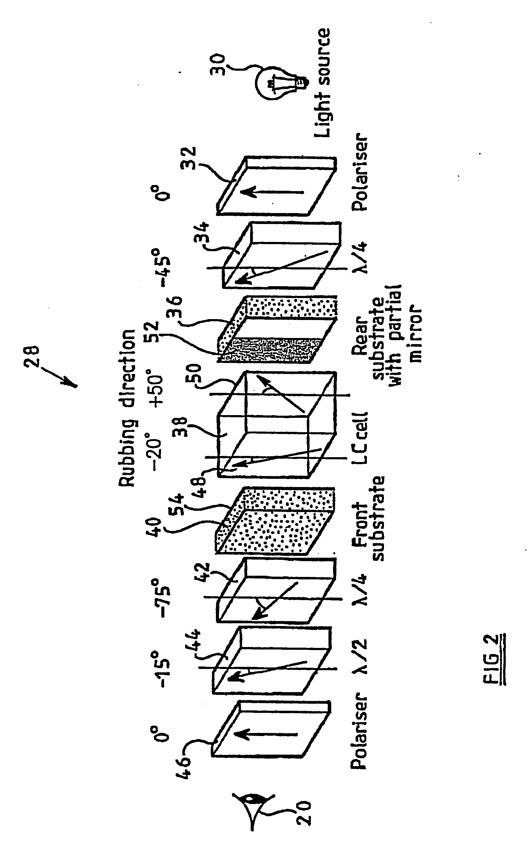
[0058]the invention, shown in FIG. 2, is a transflective liquid crystal display 28 comprising a light source 30, a rear polariser 32, rear quarterwave plate 34, rear substrate 36, liquid crystal cell 38, front substrate 40, front quarterwave plate 42, front halfwave plate 44, and front polariser 46. The location of the viewer 20 is also Indicated in FIG. 2.
[0059]The arrangement of components of the display 28 from the front polariser 46 to the rear substrate 36 (inclusive) is known from the Fujiwara reference mentioned above, except that the rear substrate 36 of the display 28 is provided with a partially reflecting (and partially transmitting) mirror (not shown separately) instead of a fully reflecting mirror.
[0060]FIG. 2 also Indicates for each of the retarders 34, 42 and 44, the angle that the slow axis of the retarder makes with respect to the angle of the absorption axes of the two polarisers 32 and 46 (which are parallel, and defined as 0 degrees). These angles are −45°, −75° ...
third embodiment
[0070]FIG. 6 shows the invention, which is a transflective display 70 providing both significantly reduced residual transmission and significantly reduced residual reflection. The components are essentially the same as those of the embodiment of FIG. 4, and the same reference numerals are therefore used. However, the display 70 differs from that of FIG. 4 in that the thickness of the front quarterwave plate (retarder) 42 is increased so that it has a retardation dΔn of substantially 150 nm.
[0071]The front and rear quarterwave plates 42 and 64 have their slow axes substantially normal to the bisetrix of the surface director orientations of the nematic LC cell 38. The two front retarders 42 and 44, and the two rear retarders 62 and 64, each form an achromatic combination retarder. The front achromatic combination retarder is modified to compensate for the residual retardation of the LC cell at finite voltages. The retardation of quarterwave plate 42 is Increased when the slow axis of ...
fourth embodiment
[0075]FIG. 8 shows the invention The components of the transflective display 100 are essentially the same as those of the embodiments of FIGS. 4 and 6, and the same reference numerals are therefore used for components which are the same. However, the nematic LC cell 38 of FIGS. 4 and 6 is replaced by a hybrid aligned nematic (HAN) LC cell 102. The cell 102 used is LC MJ96539 produced by Merck Japan and has antiparallel surface director orientation with surface pretilt of 2° and 88°, respectively, and a retardation of substantially 137.5 nm. The orientations and retardations of the other components are given in FIG. 8. The front substrate 40 also functions as a colour filter plate. The retardation of the front quarterwave plate 42 is 150 nm.
[0076]FIG. 9 shows the results of computer modelling of the electrooptic response of the embodiment of FIG. 8. The transmission results are shown by curve 104, and the reflection results by curve 106.
[0077]FIG. 9a uses the same reference numbers a...
PUM
 Abstract
Description
Claims
Application Information