Image processing for reproducing code image from original information

a code image and image processing technology, applied in the field of image processing, can solve the problems of reducing the error detection rate, reducing the accuracy of image reproduction, and reducing the convenience of users, so as to prevent the sacrifice of convenience for users

Inactive Publication Date: 2009-02-05
CANON KK
View PDF7 Cites 10 Cited by
  • Summary
  • Abstract
  • Description
  • Claims
  • Application Information

AI Technical Summary

Benefits of technology

[0014]The present invention has been developed in consideration of the above problems and provides image processing capable of preventing the convenience of users from being sa

Problems solved by technology

An error correcting rate of 25% means that it is possible to accurately extract the original information even if 25% of the two-dimensional code has been damaged.
That is, on one hand, there is an advantage that, when the error correcting rate is high, the original information can be obtained correctly even if the two-dimensional code is damaged, on the other hand, there is however a disadvantage that the two-dimensional code becomes large in size.
Conventionally, there has been a problem that the two-dimensional code is damaged more than the error correcting rate in

Method used


Image

  • Image processing for reproducing code image from original information
  • Image processing for reproducing code image from original information
  • Image processing for reproducing code image from original information

Examples


first embodiment

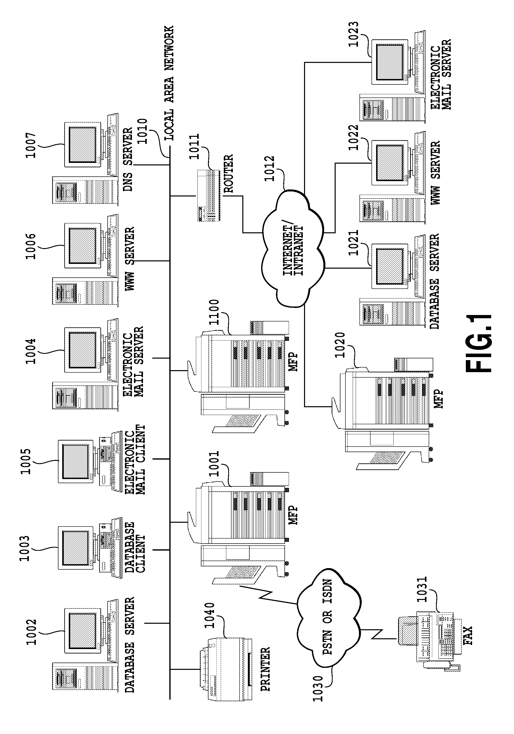
[0038]A configuration diagram of an entire network system according to the present embodiment is shown in FIG. 1. An MFP 1001 according to the present embodiment comprises a scanner and a printer. The MFP 1001 is capable of sending an image read using the scanner to a LAN 1010 or of printing out the image (forming the image on a sheet) received from the LAN 1010 using the printer. That is, the MFP 1001 comprises an image reading function and also comprises an image forming function and can operate as a printer.

[0039]The MFP 1001 also comprises a FAX transmitting function and can transmit an image read using the scanner to PSTN or ISDN 1030 using the FAX transmitting function, and can print out the image received from the PSTN or the ISDN 1030 using the printer.

[0040]A database server 1002 manages a binary image and a multiple value image read by the MFP 1001 as a database. A client 1003, which is a database client of the database server 1002, can browse, retrieve, etc., images store...

second embodiment

[0103]The processing according to a second embodiment when the MFP 1100 scans a printed matter will be described using FIG. 8.

[0104]It is assumed that a user has selected a code image read mode by means of the operation unit 2006 installed in the MFP 1100 prior to the scanning of the printed matter.

[0105]At step S801, the MFP 1100 determines whether or not there is a printed matter to be read on the document table of the scanner. This determination can be made based on a detection signal detected by a sensor provided on the document table of the scanner. When it is determined that there is a printed matter, the MFP 1100 scans (reads optically) the printed matter on the document table to produce a read image and then enters step S802. On the other hand, when it is determined that there is no printed matter, the MFP 1100 enters step S803 and displays an error message on a display screen.

[0106]At step S802, the MFP 1100 determines whether or not there exists a code image in the read im...


PUM


Abstract

It is determined whether an error detecting rate, when original information is extracted from a code image in a read image obtained by reading a sheet on which the code image is formed, is not smaller than a predetermined value. When it is not smaller than a predetermined value, a code image is reproduced from the extracted original information and the code image in the read image is replaced therewith. A barcode, which is a damaged code image, is reproduced.

Description

BACKGROUND OF THE INVENTION[0001]1. Field of the Invention[0002]The present invention relates to image processing and, more particularly, to image processing for reproducing a code image, such as a two-dimensional barcode image, from original information.[0003]2. Description of the Related Art[0004]The number of occasions is increasing, where a code image (digital watermarking image, two-dimensional barcode image, barcode image, steganography, etc.) is combined with a document image for printing using a multifunction printer (MFP).[0005]The MFP creates a code image by adding an error correcting code to original information to obtain code-added information and constructing an image from the code-added information, so that the original information can be extracted later from the code image without fail. In the present specification, adding an error correcting code is referred to as error correction coding. Further, “adding an error correcting code to obtain code-added information and ...

Claims


Application Information

Patent Timeline
IPC IPC(8): G06K9/54
CPCH04N1/32149H04N2201/0094H04N2201/3284H04N2201/327H04N2201/3269
Inventor SATO, YUUSHIKOZUKA, YASUHIRO
Owner CANON KK
Why Eureka
Try Eureka