
Error detection circuit applied to digital communication system with embedded clock

a technology of error detection and digital communication system, applied in the field of error detection, can solve the problems of poor debugging efficiency, mechanism cannot be performed immediately, and waste of data transmission channel ch

Inactive Publication Date: 2019-03-21
RAYDIUM SEMICON
View PDF9 Cites 0 Cited by
  • Summary
  • Abstract
  • Description
  • Claims
  • Application Information

AI Technical Summary

Benefits of technology

The error detection circuit of this patent can be used in a digital communication system with an embedded clock and achieve the highest error detection rate without the need for error detection encoding and decoding units in both the transmitter and receiver, as well as a codeword checking unit in the receiver. The circuit has a resettable packet error counting unit and an adjustable error tolerance threshold, which can be used to adjust design parameters of the transmitter and receiver to ensure a robust connection between them.

Problems solved by technology

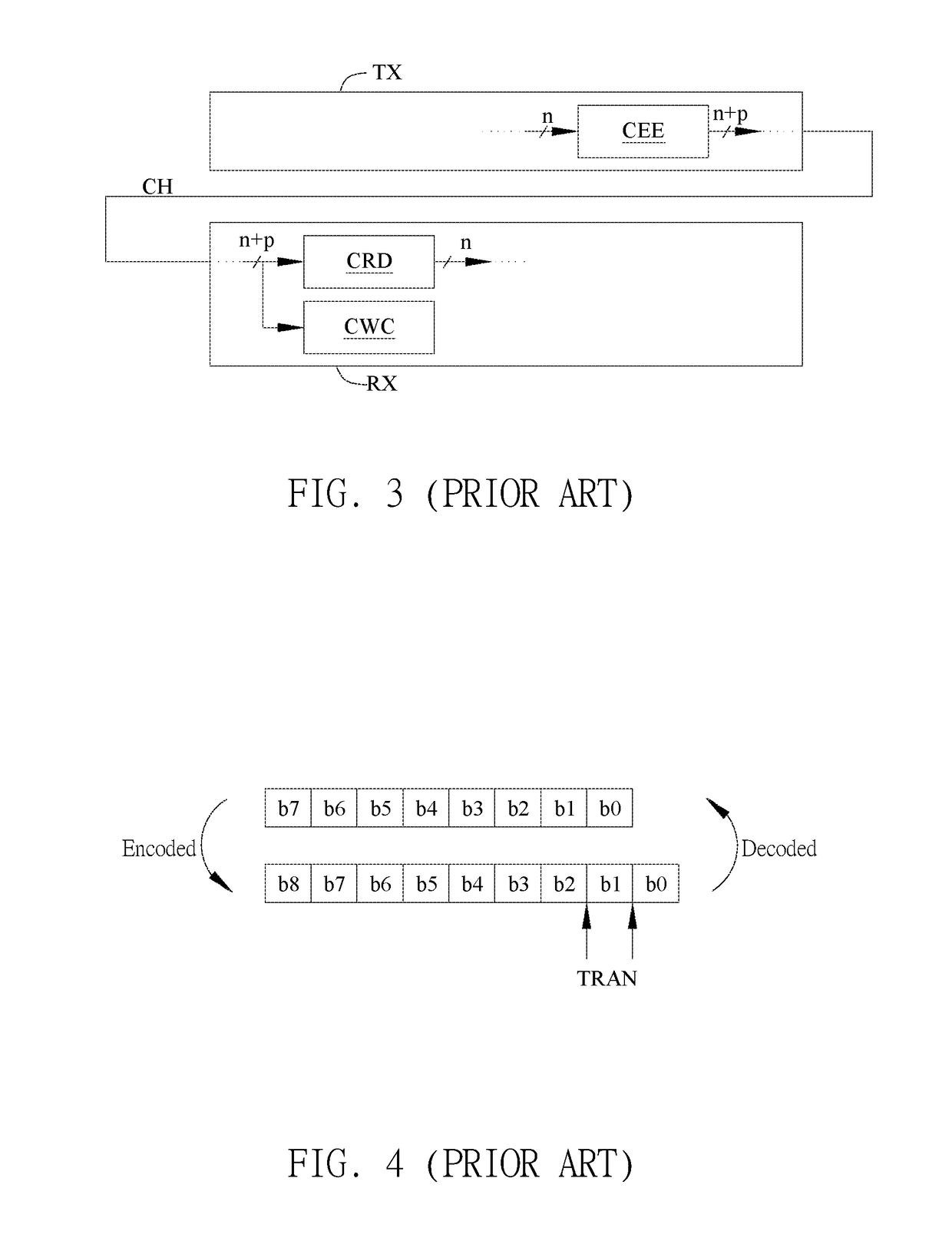
The disadvantage of this method is that the excessive number of overhead data bits of the digital data signal will cause the bandwidth of the data transmission channel CH to be wasted and the error detection encoding unit EDE and error detection decoding unit EDD are necessary to be additionally disposed in the transmitter TX and the receiver RX respectively.
And, some error detection mechanisms cannot be performed immediately, resulting in poor debugging efficiency.

Method used


Image

  • Error detection circuit applied to digital communication system with embedded clock
  • Error detection circuit applied to digital communication system with embedded clock
  • Error detection circuit applied to digital communication system with embedded clock

Examples


Embodiment Construction

[0030]A preferred embodiment of the invention is an error detection circuit. In this embodiment, the error detection circuit can be applied to a digital communication system with an embedded clock; for example, it can be applied to the high-speed serial transmission interface for video data transmission, but not limited to this.

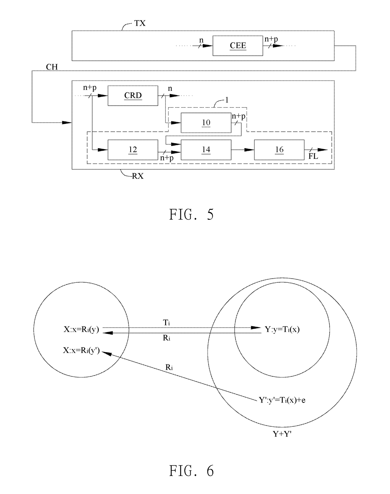
[0031]Please refer to FIG. 5. FIG. 5 illustrates a schematic diagram of the error detection circuit 1 applied to the receiver RX in this embodiment.

[0032]As shown in FIG. 5, it is assumed that the digital communication system with embedded clock includes a transmitter TX, a receiver RX and a data transmission channel CH. The transmitter TX and the receiver RX transmit data through the data transmission channel CH. The error detection circuit 1 is disposed in the receiver RX.

[0033]The transmitter TX includes a clock embedding encoding unit CEE for performing clock encoding on the digital data signal to generate a first digital encoded signal. It is assumed tha...


PUM


Abstract

An error detection circuit, applied to a digital communication system with embedded clock, includes a time delay unit, a clock embedding encoding unit, a comparing unit and a packet error counting unit. The time delay unit delays a first digital encoded signal for a period of time. The clock embedding encoding unit generates a second digital encoded signal according to a first digital decoded signal, wherein the first digital decoded signal is generated by decoding the first digital encoded signal. The comparing unit is coupled to the time delay unit and the clock embedding encoding unit respectively and compares the first digital encoded signal with the second digital encoded signal to generate a compared result. The packet error counting unit is coupled to the comparing unit and counts a packet error rate according to the compared result and then provides a flag according to the packet error rate.

Description

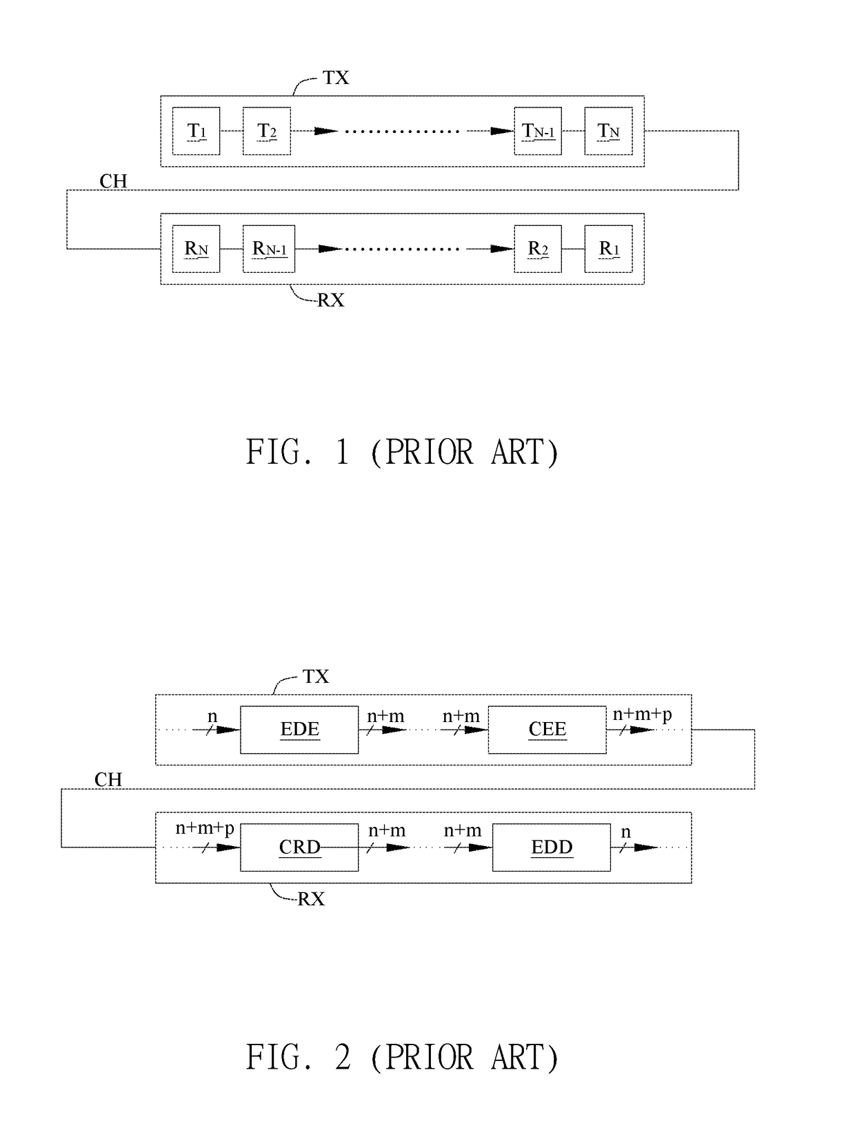
BACKGROUND OF THE INVENTION1. Field of the Invention[0001]The invention relates to error detection; in particular, to an error detection circuit applied to a digital communication system with embedded clock.2. Description of the Prior Art[0002]Referring to FIG. 1, in the conventional digital communication system, the transmitter TX can transmit data to the receiver RX through the data transmission channel CH. The transmitter TX can include N units T1˜TN and the order is T1, T2, . . . , TN-1, TN, wherein N is a positive integer; the receiver RX may include N units R1˜RN and the order is RN, RN-1, . . . , R2, R1. That is to say, the N units T1˜TN of the transmitter TX correspond to the N units R1˜RN of the receiver RX respectively, but the arrangement order and operation of the N units T1˜TN of the transmitter TX and the N units R1˜RN of the receiver RX are opposite to each other.[0003]When considering error detection in a digital communication system with an embedded clock, the trans...

Claims


Application Information

Patent Timeline
Patent Type & Authority Applications(United States)
IPC IPC(8): G06F11/07H04L7/00
CPCG06F11/0757H04L7/0054G06F11/0772H03M13/6522H04L1/242H04L25/49
Inventor HUANG, CHIH-CHUANCHEN, SUNG-BOWU, YUE-TING
Owner RAYDIUM SEMICON
Learn More