

Pulse oximeter
a pulse oximeter and pulse technology, applied in the field of pulse oximeters, can solve the problems of difficult or impossible to determine which point of time corresponds to a walking start point of time, a walking end point of time, and the inability to acquire data
- Summary
- Abstract
- Description
- Claims
- Application Information
AI Technical Summary
Benefits of technology
Problems solved by technology
Method used
Image

Examples
first embodiment
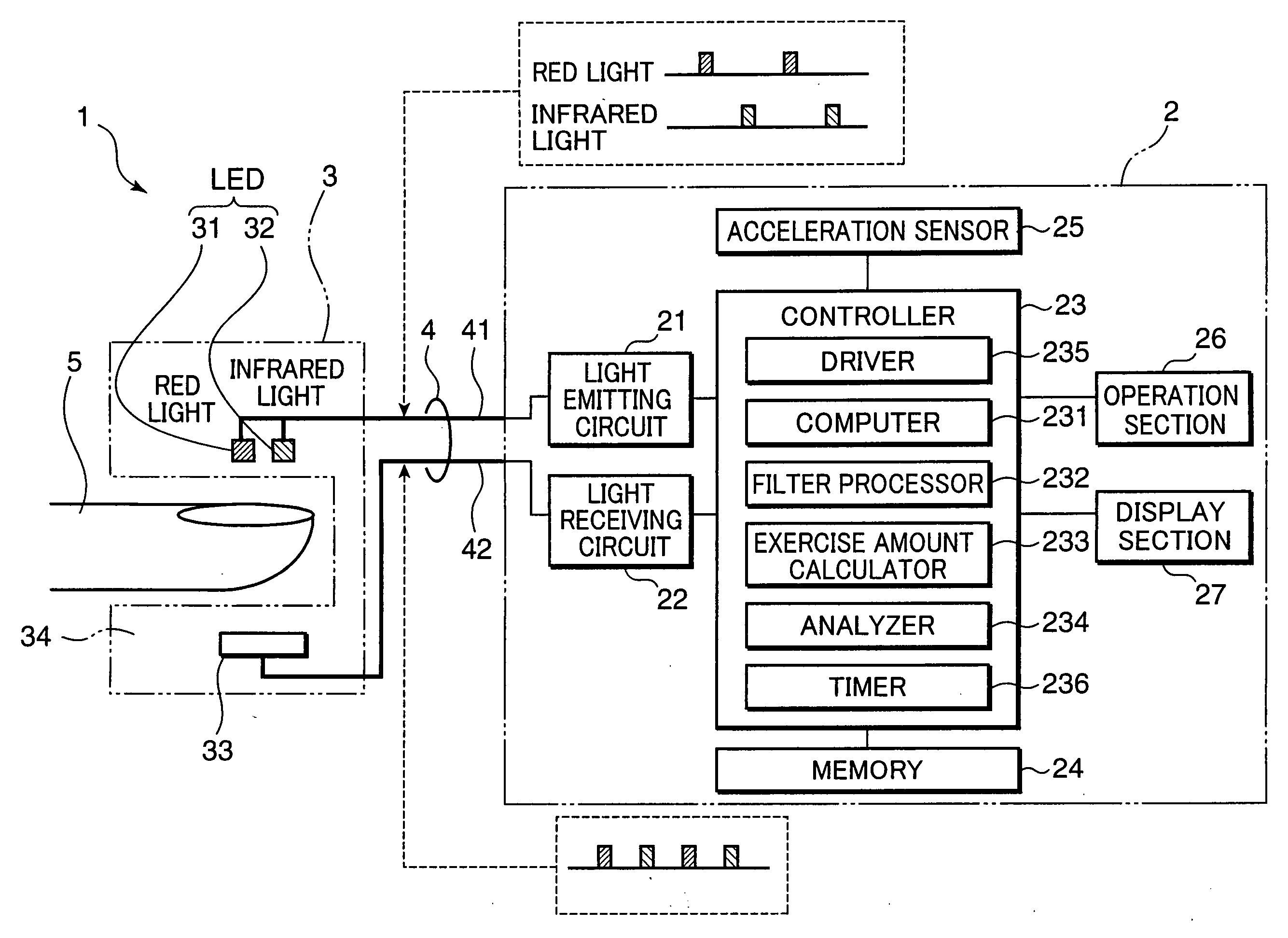
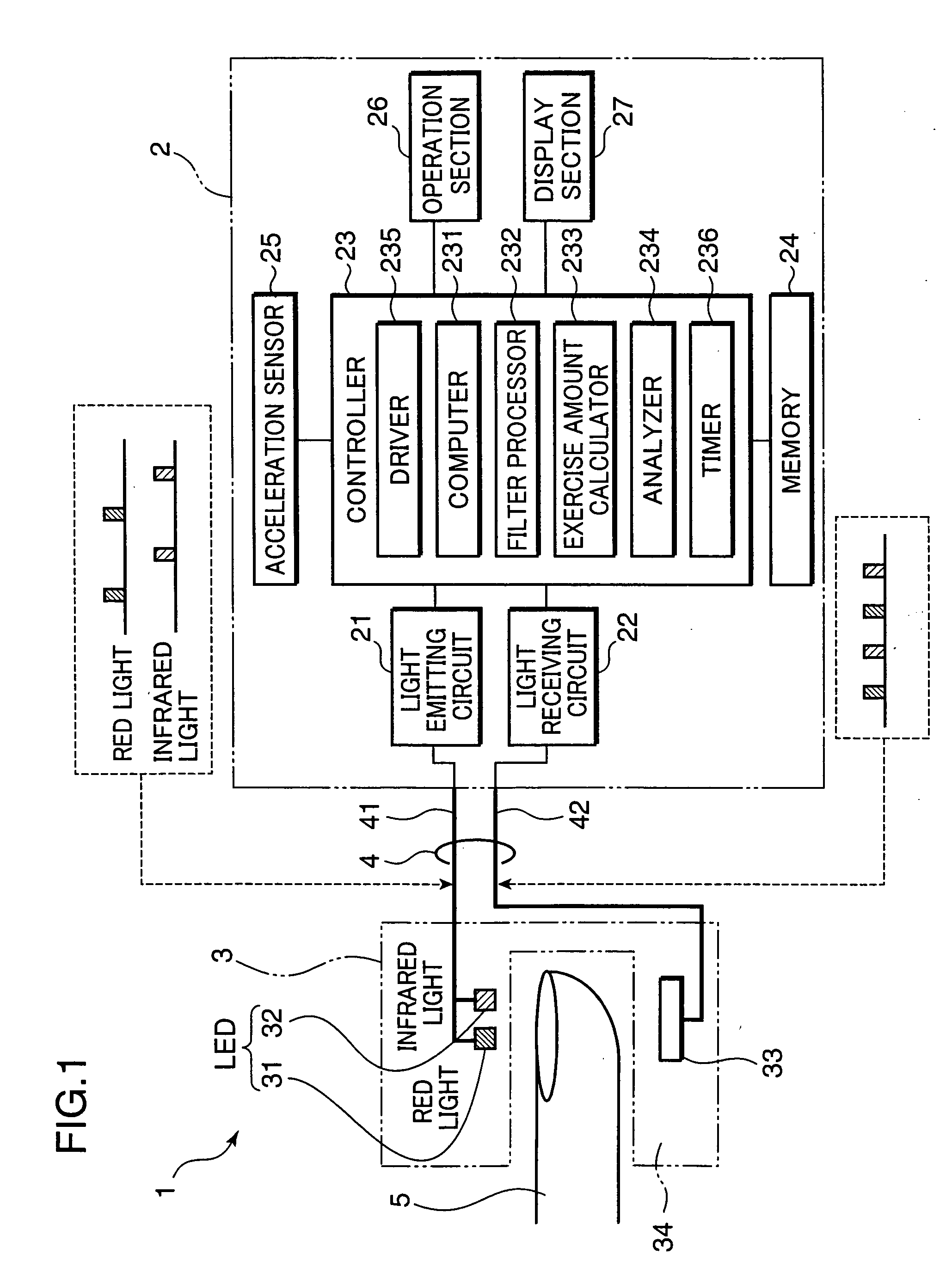
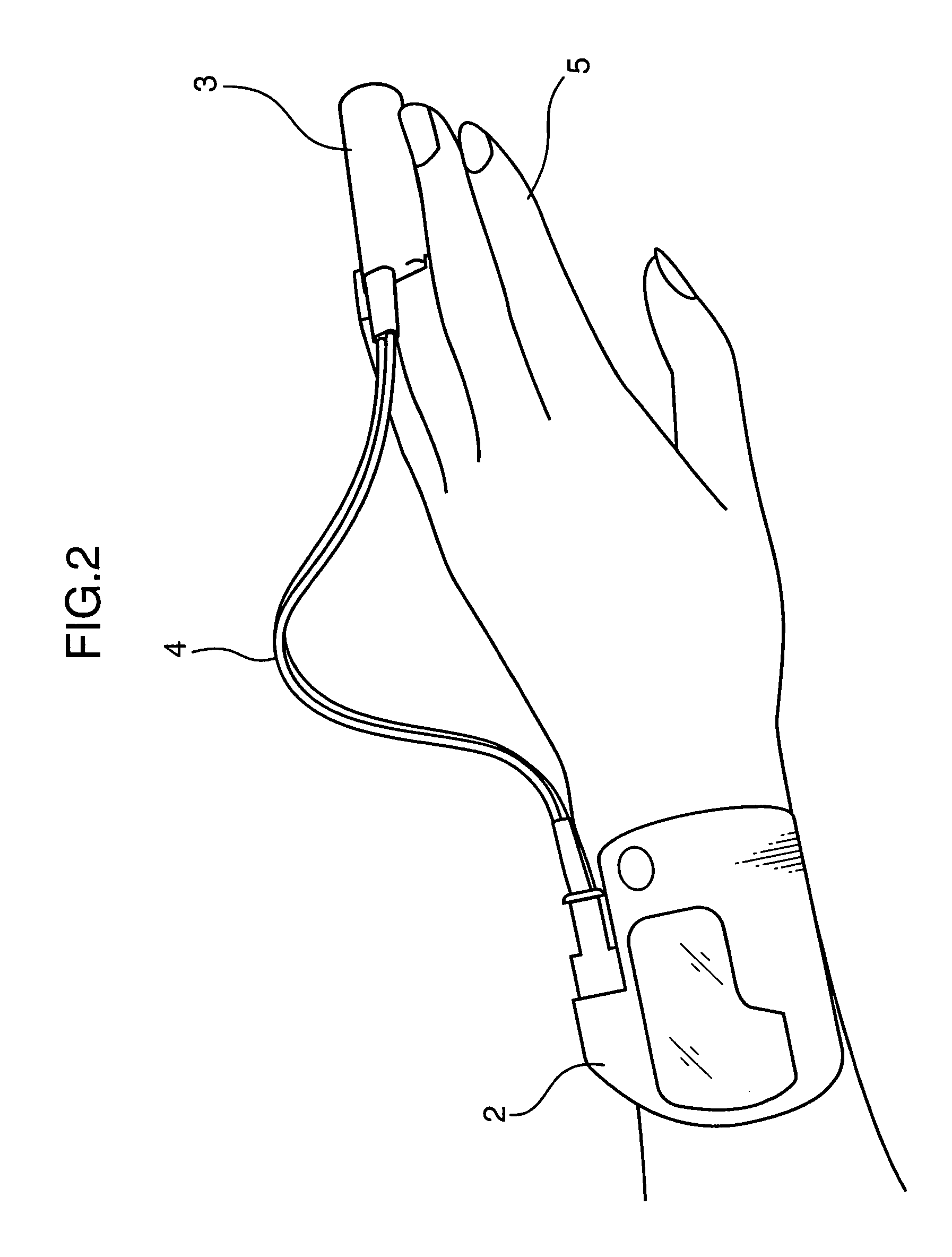
[0020]FIG. 1 is a block diagram showing an arrangement of a pulse oximeter 1 as the first embodiment of the invention. FIG. 2 is a perspective view showing an external appearance of the pulse oximeter 1.
[0021]Referring to FIGS. 1 and 2, the pulse oximeter 1 primarily includes a body portion 2, a probe portion 3, and a cable 4 for connecting the body portion 2 and the probe portion 3.
[0022]The body portion 2 includes a light emitting circuit 21, a light receiving circuit 22, a controller 23 constituted of e.g. a CPU (Central Processing Unit), a memory 24 constituted of e.g. a flash memory, as a storage, an acceleration sensor 25 as a detector, an operation section 26 constituted of e.g. a pressing button, and a display section 27 constituted of e.g. a liquid crystal display device. The flash memory is a rewritable non-volatile memory element. The probe portion 3, the light emitting circuit 21, the light receiving circuit 22, and the controller 23 constitute a first measuring section....
second embodiment
[0043]FIG. 5 is a block diagram showing an arrangement of a pulse oximeter 41 as a second embodiment of the invention. The pulse oximeter 41 shown in FIG. 5 is similar to the pulse oximeter 1 in the first embodiment. Elements of the pulse oximeter 41 substantially equivalent or identical to those of the pulse oximeter 1 are indicated by the same reference numerals, and description thereof is omitted herein. A feature of the pulse oximeter 41 is that the pulse oximeter 41 is provided with a position information acquirer 45, as a detector for detecting the gait of a subject. In the example of FIG. 5, a GPS (Global Positioning System) receiver is used as the position information acquirer 45. Since the pulse oximeter 41 is provided with the position information acquirer 45, a controller 43 in a body portion 42 functionally includes a moving amount calculator 433 for calculating an exercise amount of the subject based on an output from the position information acquirer 45, and an analyze...
third embodiment
[0046]FIG. 6 is a block diagram showing an arrangement of a pulse oximeter 51 as a third embodiment of the invention. The pulse oximeter 51 shown in FIG. 6 is similar to the pulse oximeters 1 and 41 in the first and the second embodiments. Elements of the pulse oximeter 51 substantially equivalent or identical to those of the pulse oximeter 1, 41 are indicated by the same reference numerals, and description thereof is omitted herein. A feature of the pulse oximeter 51 is that the pulse oximeter 51 is provided with a revolution counter 55, as a detector for detecting the gait of a subject. The revolution counter 55 is mounted on a carrier which travels along with a subject. Examples of the carrier include a trolley for transporting an oxygen bomb, an infusion bottle, or the like to be carried along with a subject, and a walking aid device to be operated by a subject.
[0047]Since the pulse oximeter 51 is provided with the revolution counter 55, a controller 53 in a body portion 52 func...
PUM
 Abstract
Description
Claims
Application Information